
In this blog post, I’ll share my journey of reverse engineering a TP-Link TL-WR850N (Version 3.0) router. This exploration led to some interesting discoveries about its security implementation and firmware structure. Through careful hardware analysis and firmware extraction, I uncovered several potential security vulnerabilities and gained insights into the router’s internal architecture. Join me as I walk through the process of identifying UART interfaces, extracting firmware via SPI, and analyzing the device’s security measures. This investigation not only revealed the router’s technical inner workings but also highlighted important security considerations for IoT devices in general.
The Target
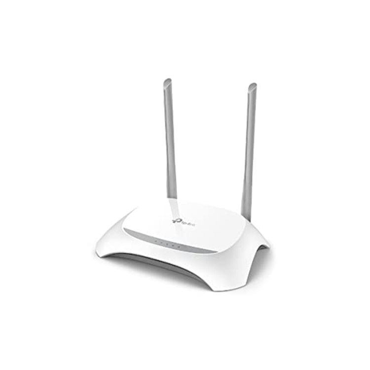
The subject of our investigation is the TP-Link TL-WR850N router, a common household device that turned out to be a treasure trove of security insights.
Hardware Setup
Tools Required
Hardware Tools
- Screwdriver (for opening the router)
- Header pins (for the UART pin holes)
- Soldering iron (soldering the header pins)
- FTDI232R (for UART communication)
- CH341A programmer (for firmware dump off the SPI chip)
- Jumper Wires
Software Tools
- Virtual Box: Kali Linux
- flashrom
- binwalk
- hashcat
- md5sum
- screen (for UART connection)
- CH341A drivers
The Investigation Process
1. Hardware Analysis
Router Back Side
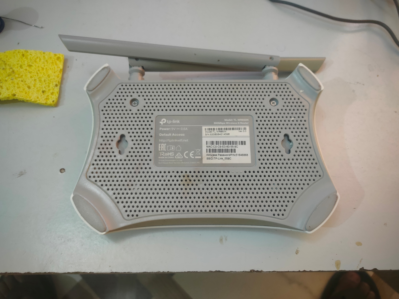
From examining the router’s back side label, I can deduce several important details:
Model Information: The label clearly shows this is a TP-Link TL-WR850N router, which helps identify the specific hardware and firmware versions to target.
Version Number: The label indicates this is Version 3.0, which is crucial for finding the correct firmware and documentation.
Default Credentials: The label displays the default login credentials (TP-Link_559C/51646868) which are essential for initial access.
MAC Address: The label shows the device’s MAC address (C0-C9-E3-60-55-9C), which can be used to identify the manufacturer and potentially track the device on a network.
Serial Number: The unique serial number is visible, which can be used to verify the device’s authenticity and potentially find specific firmware versions.
Power Requirements: The label specifies the input voltage (9V DC) and current requirements, which are important for power analysis and potential hardware modifications.
PCB Analysis
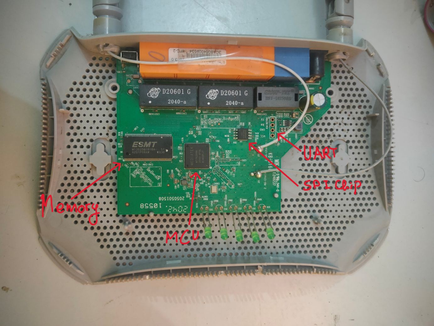
After opening the router, I carefully examined the PCB to identify key components:
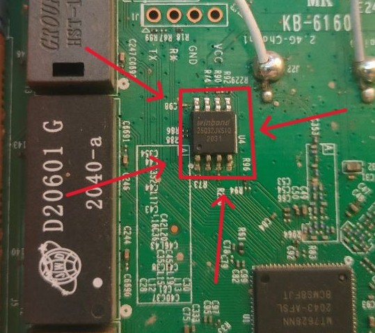
SPI Flash Chip: Located near the edge of the board, identified by its 8-pin SOIC package and typical SPI pinout (MOSI, MISO, SCK, CS). The chip was labeled with “25Q32”, indicating it’s a 32Mbit (4MB) SPI flash memory chip commonly used for storing firmware and configuration data.
RAM: Found next to the main MCU, identified by its rectangular package and multiple address/data lines. The part number “W13S2561616A” indicates it’s a 256Mbit (32MB) DDR2 SDRAM chip used for temporary data storage and program execution.
Main MCU: The large chip in the center of the board, marked with “MEDIATEK MT7628NN”, which is a MIPS-based system-on-chip (SoC) that integrates a 580MHz CPU, 2.4GHz WiFi radio, and various peripheral interfaces for router functionality.
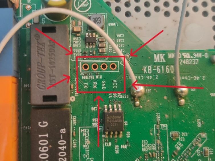
UART Pins: Identified by a 4-pin header near the edge of the board. I was lucky that the pins were labeled on the PCB silkscreen, so I didn’t have to use the multimeter to identify them. The pins were clearly marked as:
- VCC (3.3V)
- GND
- TX (transmit)
- RX (receive)
2. Firmware Extraction Setup
Kali Linux Setup
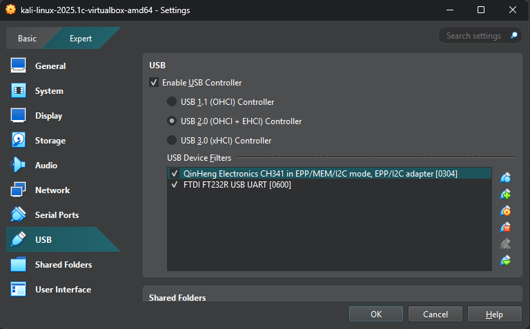
The image above shows the USB port configuration in VirtualBox for the Kali Linux VM. Two USB devices are enabled:
- CH341A Programmer - Used for SPI flash memory reading
- FTDI232 - Used for UART communication
These USB devices are essential for hardware reverse engineering as they allow direct communication with the router’s components.
CH341A Connection
The images below show the setup process for connecting the CH341A programmer to the router’s SPI flash memory chip:
The first image shows the SPI flash memory chip (25Q32) on the router’s PCB, which stores the firmware and configuration data.
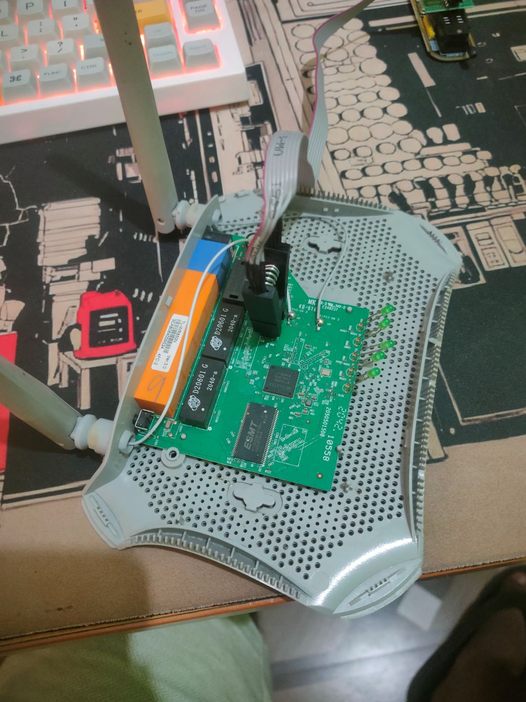
The second image demonstrates how the CH341A programmer’s clip is connected to the SPI chip’s pins, allowing us to read and write data to the flash memory.
Multiple Chip Detection

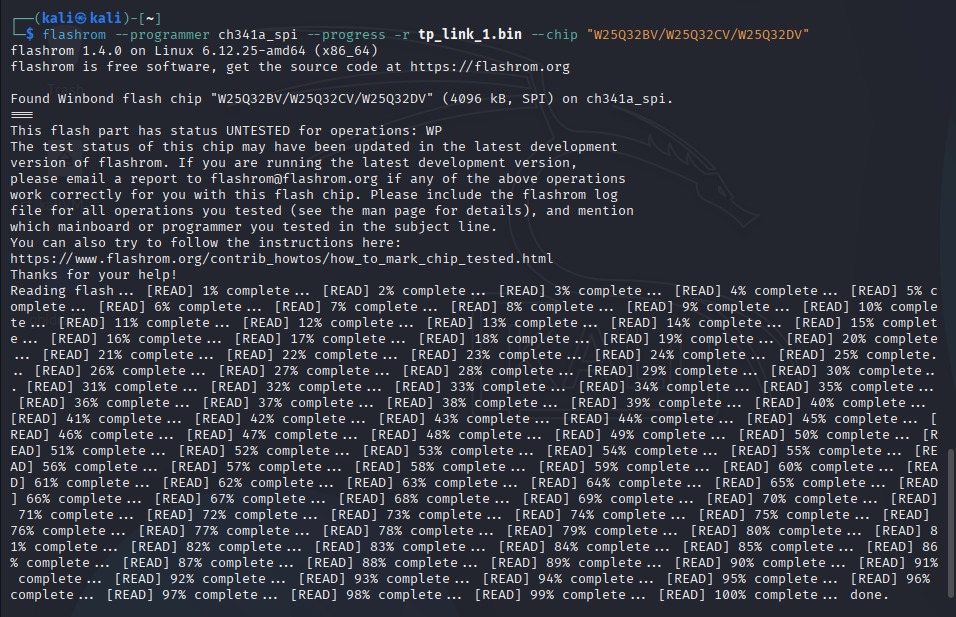
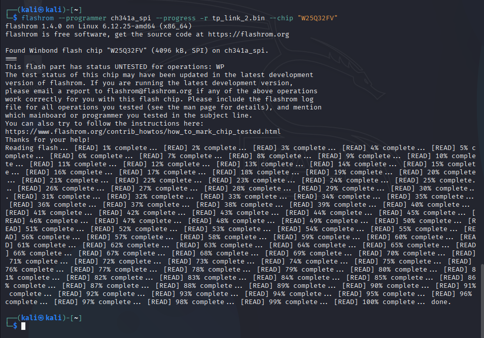
When using flashrom with the CH341A programmer to read the SPI flash memory, multiple chips were detected despite physically connecting to a single 25Q32 chip. This occurred because flashrom’s chip detection mechanism attempts to identify the connected chip by sending different initialization sequences and checking for responses. The 25Q32 chip is compatible with multiple chip families and protocols, causing flashrom to detect several potential matches. This is a common occurrence with SPI flash chips that follow standard protocols, and we can safely proceed with any of the detected chip options since they share the same basic functionality.
This information is valuable for several reasons:
- It helps verify that our physical connection to the chip is working correctly
- It provides flexibility in choosing the most appropriate chip profile for our operations
- It can be useful for identifying compatible replacement chips if the original needs to be replaced
- It demonstrates the interoperability of SPI flash chips across different manufacturers and protocols
3. Firmware Extraction and Analysis
Firmware Dump Process
# Firmware Dump
flashrom —programmer ch341a_spi —progress -r tp_link.bin —chip "<Chip-name>"
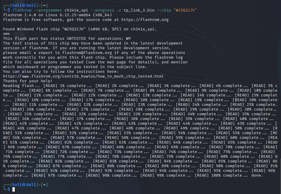
Verification
# MD5 Checksum Verification
md5sum tp_link*
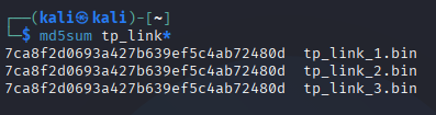
The MD5 checksum verification is a crucial step in ensuring the integrity of the firmware dump. By comparing the MD5 hashes of all three firmware dumps, we can confirm that:
- All three dumps are identical, indicating a successful and consistent read operation
- The data wasn’t corrupted during the extraction process
- We can proceed with analyzing any of the three files since they contain the same data
This verification step is essential in hardware reverse engineering as it helps ensure the reliability of our extracted firmware before proceeding with further analysis.
Initial Analysis
# Binwalk Analysis
binwalk firmware.bin
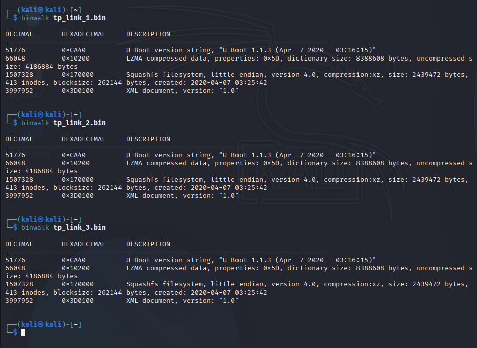
The binwalk analysis of the firmware reveals several important components:
U-Boot Version String
- Found at offset 0xCA40
- Shows “U-Boot 1.1.3”
- This is the bootloader version used by the router
LZMA Compressed Data
- Located at offset 0x10200
- This is a compression algorithm often used for firmware components
- May contain additional system files or resources
Squashfs Filesystem
- Found at offset 0x170000
- Little endian format
- Version 4.0
- Uses XZ compression
- Contains the main operating system files and applications
XML Document
- Located at offset 0x3D0100
- Version 1.0
- Likely contains configuration or metadata information
This analysis provides valuable insights into the firmware structure and helps identify the main components that can be extracted for further analysis.
Since the MD5 Checksums are same as well as the content of all bin files, So a single file is chosen for extraction.
Extraction
# Binwalk Extraction
binwalk -e firmware.bin
.png)
4. Security Analysis
Interesting Find
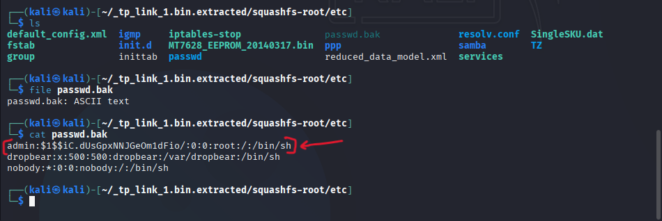
During the firmware analysis, I discovered a backup password file that revealed critical security vulnerabilities in the router’s authentication system. (Later will be used in UART Analysis)
Password File Discovery
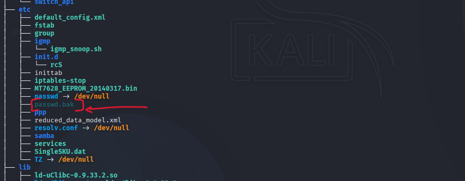
Password File Content
Password Cracking
Password Cracking Methodology
The password cracking approach was chosen based on several key factors:
Hash Identification
- The
$1$prefix in the hash indicated MD5(Unix) format - This is a legacy hashing method commonly used in older Unix systems
- The format follows the pattern:
$1$salt$hashed_password
- The
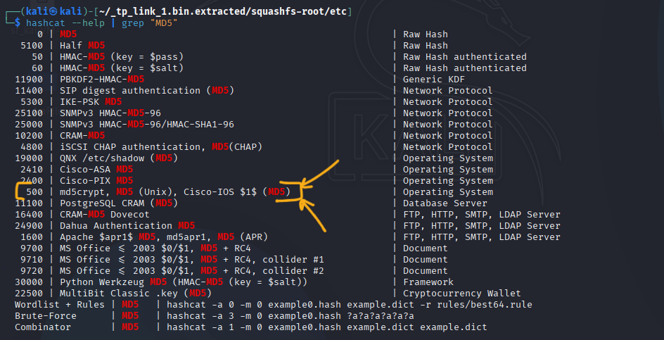
Hashcat Mode Selection
- Mode 500 was specifically chosen because:
- It matches the MD5(Unix) format identified in the password file
- It’s designed for cracking Cisco-IOS style MD5 hashes
- It’s compatible with the
$1$format found in the backup password file
- Mode 500 was specifically chosen because:
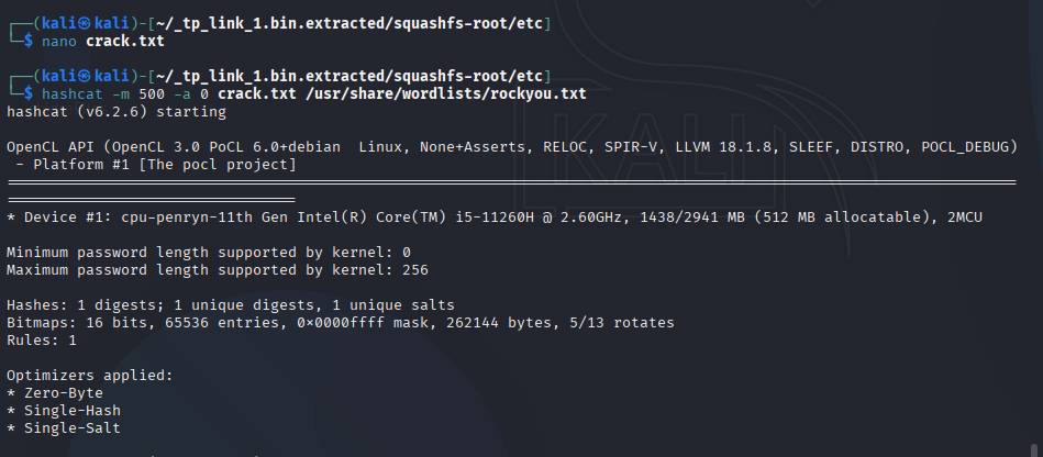
Attack Method
- Dictionary attack (-a 0) was selected because:
- It’s efficient for common passwords
- Router manufacturers often use default or simple passwords
- It’s less resource-intensive than brute force attacks
- Dictionary attack (-a 0) was selected because:
Wordlist Selection
- A custom wordlist was used containing:
- Common router default passwords
- Manufacturer-specific default credentials
- Simple numeric combinations
- A custom wordlist was used containing:
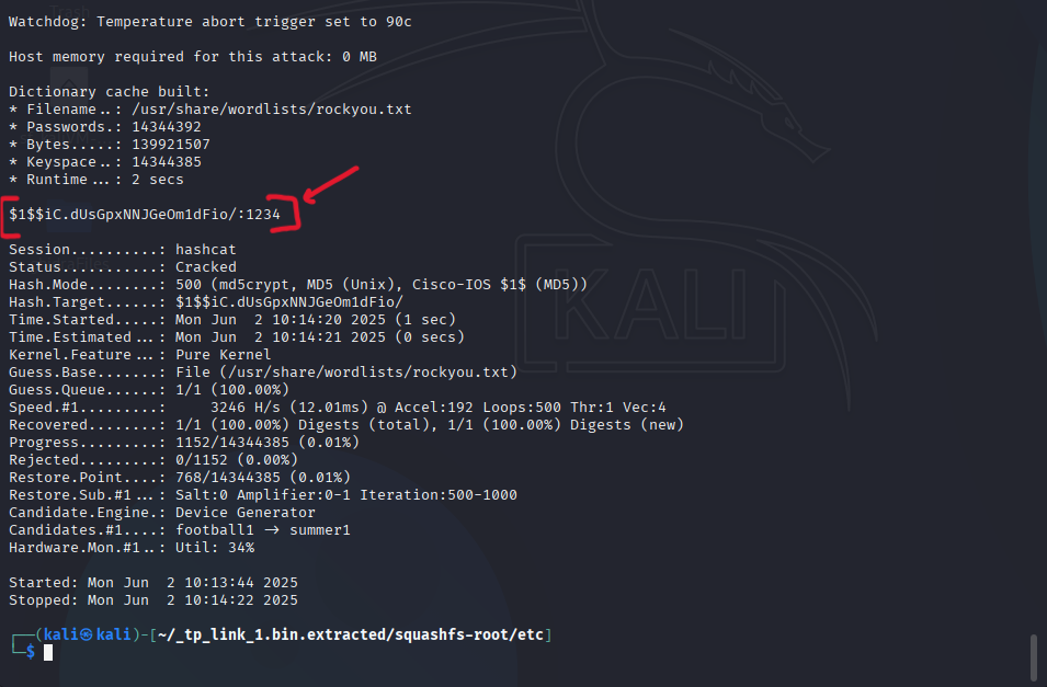
This methodology successfully revealed the password “1234”, demonstrating the weak security implementation in the router’s authentication system.
# Hashcat Mode Selection
hashcat --help | grep "MD5"
# Mode 500: MD5(Unix) Cisco-IOS $1$(MD5)

# Hashcat Command
hashcat -m 500 -a 0 hash.txt wordlist.txt
5. UART Access
FTDI Connection
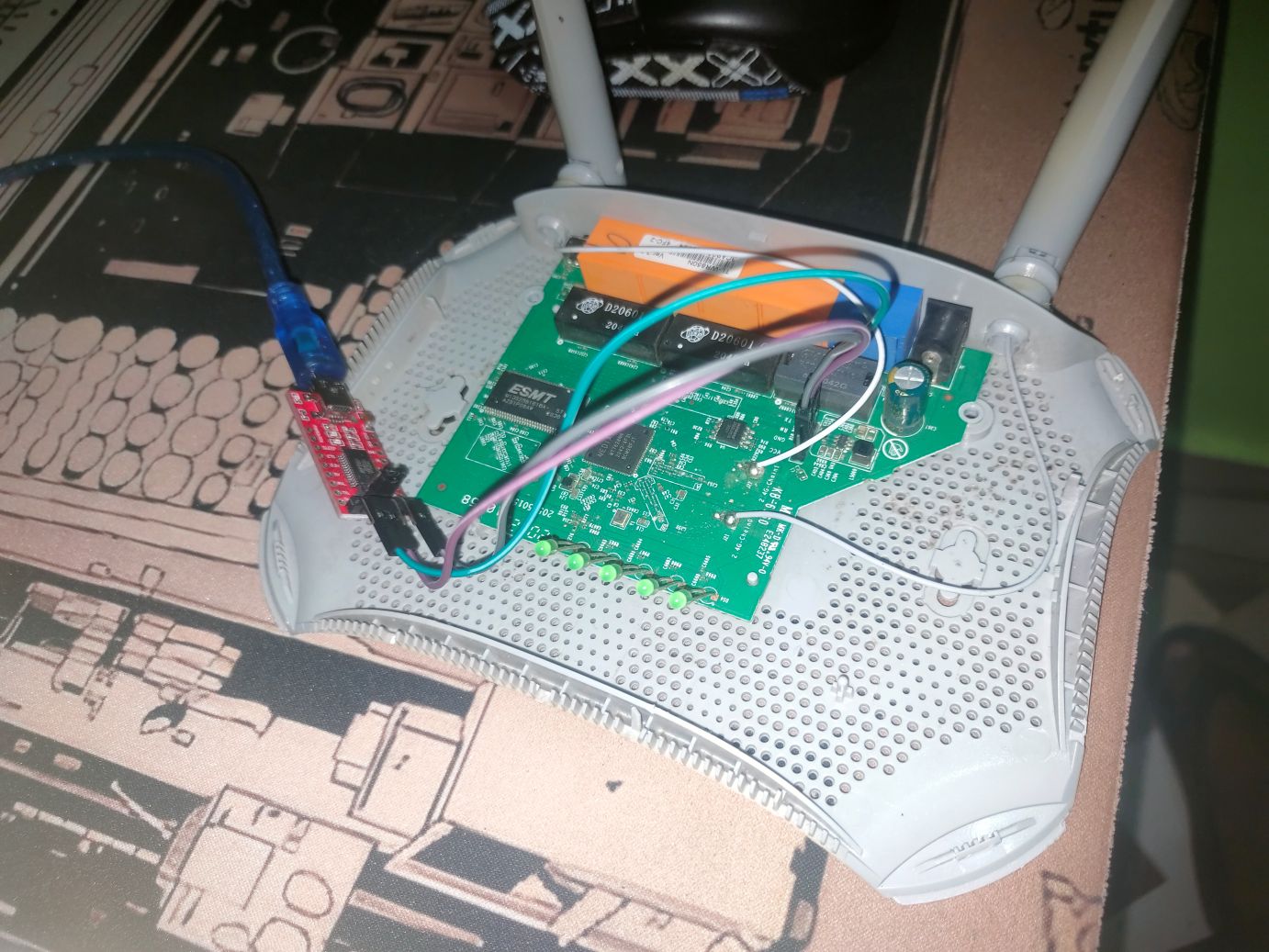
The first image shows the UART pins exposed on the router’s PCB, which are used for serial communication. I soldered header pins to these UART pins for easy access using jumper wires. The second image demonstrates the connection between these UART pins and the FTDI232R USB-to-TTL converter. The connection follows this pinout:
- GND pin on the router connects to GND on the FTDI232R
- TX (Transmit) pin on the router connects to RX (Receive) on the FTDI232R
- RX (Receive) pin on the router connects to TX (Transmit) on the FTDI232R
This cross-connection (TX to RX and RX to TX) is necessary because the transmit pin of one device needs to connect to the receive pin of the other device to establish proper serial communication. The GND connection ensures both devices share the same reference voltage level.
Port Verification
# FTDI Port Check
ls /dev/ttyUSB*
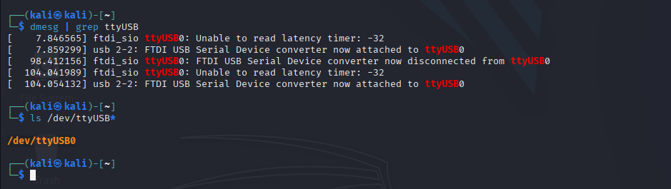
The port verification step is crucial for several reasons:
Device Recognition
- Ensures the FTDI232R is properly detected by the system
- Confirms the USB-to-TTL converter is functioning correctly
- Verifies the correct driver installation
Port Identification
- Identifies the specific port assigned to the FTDI232R (e.g., /dev/ttyUSB0)
- Essential for configuring the serial connection parameters
- Prevents connection attempts to incorrect ports
Troubleshooting
- Helps diagnose connection issues
- Verifies physical connection integrity
- Confirms proper USB enumeration
Security
- Ensures we’re connecting to the intended device
- Prevents accidental connection to other serial devices
- Reduces risk of connecting to wrong hardware
This verification step is a fundamental part of the UART debugging process, ensuring reliable and secure serial communication with the router’s debugging interface.
UART Access
# Screen Command
screen /dev/ttyUSB0 115200

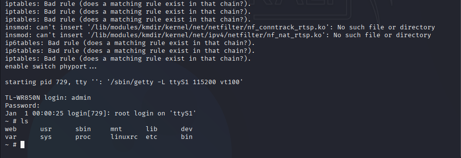
The screen command establishes a serial connection to the router’s UART interface. The parameters used are:
/dev/ttyUSB0: The serial port assigned to the FTDI232R115200: The baud rate for serial communication
Once connected, we gain access to the router’s boot sequence and eventually the admin shell. The second image shows successful access to the admin shell, where we can execute commands with root privileges. This unrestricted access via UART represents a significant security vulnerability, as it bypasses all software-based security measures and provides direct access to the router’s operating system. The boot sequence provides several advantages for security analysis:
- The log file shows all executables running during router setup
- We can identify potentially vulnerable scripts and services
- With admin level shell access, exploiting these vulnerabilities becomes straightforward
6. Exploring the Config Partition from Firmware
While analyzing the UART logs obtained through the serial port, I noticed an interesting entry in the firmware’s file structure: a dedicated config partition.
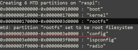
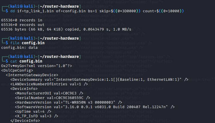
Curious about its contents, I used the dd command to extract the partition for further analysis:
# Extracting the config partition
dd if=tp_link_1.bin of=config.bin bs=1 skip=$((0x3D0000)) count=$((0x10000))
Upon inspecting the extracted partition, I discovered several sensitive details:
Device Details
The partition contained device-specific information such as serial numbers, Software & Hardware Versions, and other identifiers.
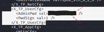
Admin Password for Router Configuration
Surprisingly, the admin password for the router’s web configuration interface was stored in plain text within this partition.
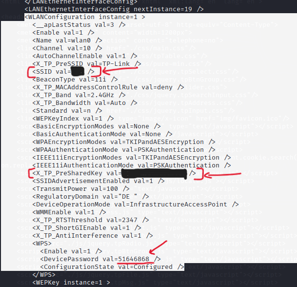
Saved WiFi SSID and Password
Even more concerning, the partition also stored the WiFi SSID and password in an easily accessible format.
Security Implications
Storing sensitive information such as admin and WiFi credentials in an unencrypted config partition poses a significant security risk. Anyone with physical access to the device and basic technical skills could extract this data, compromising both the device and the network it protects.
Security Findings
1. Password Storage Vulnerability
The most significant finding was the outdated password storage mechanism:
# Contents of /etc/passwd.bak
admin:$1$$iC.dUsGpxNNJGeOm1dFio/:0:0:root:/:/bin/sh
This revealed:
- Passwords stored in
/etc/passwdinstead of/etc/shadow - Use of MD5 hashing (mode 500)
- Hardcoded admin credentials
2. UART Access
The router provided unrestricted shell access via UART, allowing:
- Direct admin shell access with known password (i.e. 1234 - got after hashcat)
- Full system control
Conclusion
This investigation revealed several critical security issues:
- Outdated password storage mechanisms
- Unrestricted UART access
- Exposed debugging interfaces
- Hardcoded credentials
Recommendations
For router manufacturers:
- Implement modern password storage (shadow files)
- Disable or secure UART access in production
- Remove or secure debugging interfaces
- Use secure credential storage
For users:
- Regularly update firmware
- Change default credentials
- Disable unnecessary services
- Monitor for suspicious activity
My Journey into Router Security
My investigation of consumer router security revealed critical vulnerabilities in common networking equipment. What began as curiosity about internal device workings led to significant security discoveries.
Key Findings
The investigation uncovered two major issues:
Outdated Password Storage: Passwords were stored in
/etc/passwdusing MD5 hashing instead of the more secure/etc/shadow, with hardcoded admin credentials present.Unrestricted UART Access: The device had open UART debugging interfaces, allowing full administrative access with a simple connection and default password.
Security Lessons
This research highlighted important security principles:
- Default configurations often contain serious vulnerabilities
- Security through obscurity is ineffective
- Proper security implementation is crucial
- Physical access security matters
The findings demonstrate how consumer devices often prioritize convenience over security, emphasizing the need for better security standards in the industry.
Files and Resources
Note: This research was conducted for educational purposes only. Always ensure you have proper authorization before performing security testing on any device.