
Ever looked at your keyboard and thought, “You know what would make this better? If I could rip it in half!” Well, that’s exactly what I did. Join me on a wild ride through cardboard carnage, soldering shenanigans, and firmware fumbles as I build my very own split keyboard from scratch. Spoiler: It actually works (eventually)😅!
Table of Contents
- Motivation & Initial Ideas
- Designing in Ergogen
- DXF to SVG: File Conversion
- Printing & Manual Plate Cutting
- Switches, Encoder, and Plate Assembly
- Soldering: Diodes, Wires, and Headers
- Firmware Development with QMK
- Debugging: Split Connection & Encoders
- Final Assembly & Keycaps
- What’s Next? OLEDs and PCBs
- Useful Links & Resources
- Bill of Materials (BOM) & Affiliate Links
Motivation & Initial Ideas
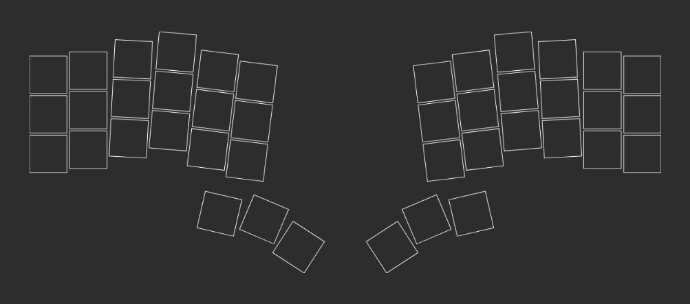
Why settle for a boring, off-the-shelf keyboard when you can build one that fits your hands like a glove? I wanted something ergonomic, something unique, something that would make my desk look like a hacker’s lair. My original plan was to slap an OLED screen on each half (because, why not?), but the siren song of a working keyboard was too strong. OLEDs and a custom PCB? That’s a quest for another day!
Keyboard Outline
Designing in Ergogen
Enter Ergogen, the magical YAML-based tool that lets you design custom keyboards with code instead of CAD. Ergogen works by letting you define your keyboard’s layout, outline, and even switch footprints using a simple configuration file. This means you can tweak the number of keys, their positions, and the overall shape just by editing a few lines of YAML—no need to wrestle with complicated vector graphics or mechanical design software.
I started by reading through their docs and browsing community examples to get a feel for how the system works. Ergogen’s workflow is modular: you define “points” (the coordinates for each key), “outlines” (the board’s shape), and “cases” (for generating the actual plate or PCB). For my split keyboard, I focused on creating two mirrored halves, each with 21 keys, plus a spot for a rotary encoder on each side.
Here’s a quick breakdown of my Ergogen process:
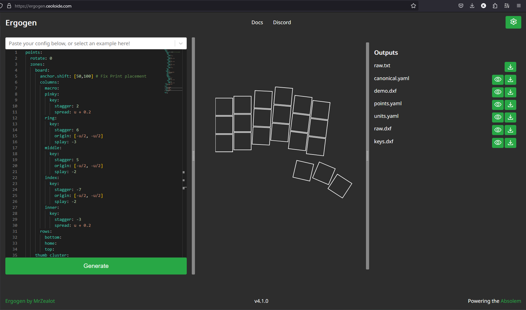
- Points: I mapped out the grid for each half, adjusting the stagger and splay to fit my hand’s natural resting position. This took a bit of trial and error—Ergogen’s live preview was a lifesaver!
- Outlines: I defined the outer contour to hug the keys closely, giving the board a compact, wing-like appearance. I also added a small “tab” on each half for the TRRS jack and microcontroller.
- Switch Cutouts: Each key position was set to have a 14mm square cutout, perfect for MX-style switches. I double-checked the measurements to ensure a snug fit.
- Encoder Cutout: I added a circular cutout for the EC11 rotary encoder, making sure it was positioned for easy thumb access.
After a few iterations—lots of YAML tweaks, previewing, and exporting—I generated the final .dxf files for the plates. Ergogen’s output is clean and ready for further editing or direct fabrication.
If you’re curious, here’s a snippet from my Ergogen YAML for the left half’s key grid:
DXF to SVG: File Conversion
Ergogen gave me a .dxf file, but my artistic ambitions demanded an .svg. Enter Convertio, the unsung hero of file conversion. I imported the SVG into Inkscape, double-checked that every switch hole was a perfect 14mm, and set the print scale to 100% on A4 paper. Because nothing says “precision engineering” like a home printer and a ruler.
Check out my Ergogen files:
My Ergogen YAML and output files
Feel free to fork, remix, or use them as a starting point for your own build!
Printing & Manual Plate Cutting
Here’s where things got… crafty. With acrylic sheets nowhere to be found in my town, I grabbed a trusty 1.5mm cardboard sheet. I printed the design, glued it on, and began the painstaking process of cutting out each switch hole by hand. Pro tip: If you value your sanity (and your fingers), get a pre-cut plate or use a CNC service like Robu.in. My hands may never forgive me.
After a few hours of slicing and dicing, I had two plates that looked suspiciously like wings. Maybe I was building a keyboard, maybe I was summoning a cardboard phoenix. Either way, it was starting to look cool.
Switches, Encoder, and Plate Assembly
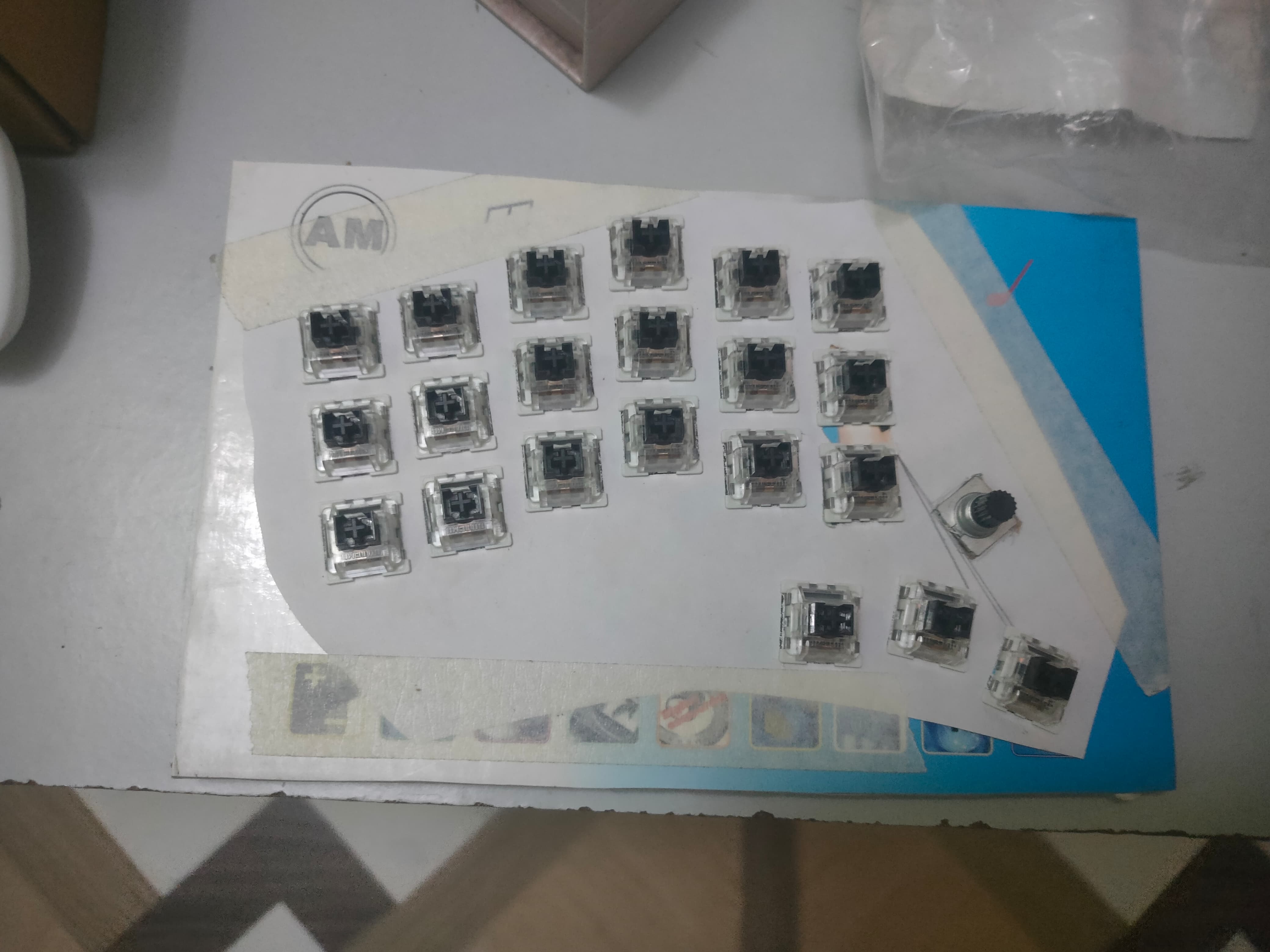
Now for the most hands-on, tactile part of the build: installing the switches and rotary encoder. For this project, I used Outemu Black MX-style mechanical switches—these are linear switches with a slightly heavier actuation force, which I personally prefer for both typing and gaming. Each switch snaps into its 14mm cutout with a satisfying click. If you’ve never installed switches before, it’s a bit like popping bubble wrap, but with more purpose!
For the encoder, I chose a basic EC11 rotary encoder with a push button. It fits snugly into its dedicated hole on the plate. The encoder will later be wired up to control volume or other functions in QMK firmware.
Assembly tips:
- Test-fit every switch before final assembly. Cardboard can flex or compress, so you may need to gently widen some holes with a craft knife for a perfect fit.
- Support the plate from underneath as you press in the switches to avoid bending or tearing the cardboard.
- Double-check switch orientation so the pins all face the same direction for easier soldering later.
- The encoder’s pins should be accessible from the back for easy wiring.
After all the Outemu Black switches and the encoder were in place, I trimmed the plate edges with a sharp blade to clean up any rough spots and give the board a more polished look. At this point, my cardboard prototype was really starting to look and feel like a real keyboard—albeit a very lightweight one!
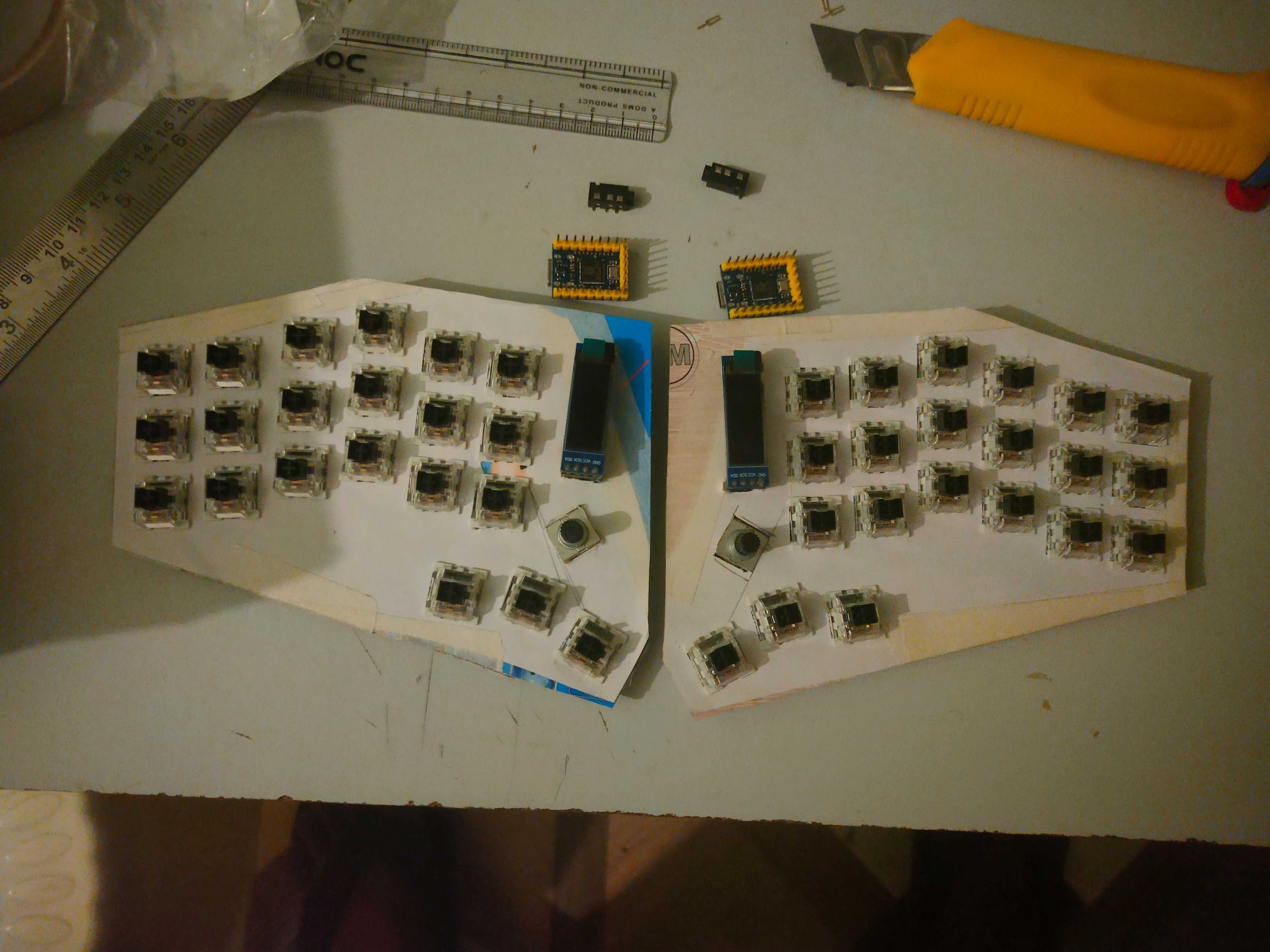
Parts used:
- 42x Outemu Black MX-style switches (linear, heavy)
- 2x EC11 rotary encoder (with push button)
- Cardboard plate (1.5mm thick)
- Craft knife, ruler, and patience
Next up: wiring the matrix and soldering everything together!
Soldering: Diodes, Wires, and Headers
Now, onto the soldering stage—a.k.a. “How many times can I burn my fingers before learning my lesson?” This is where the keyboard really starts to come together electrically, and attention to detail pays off.
1. Diodes:
Each switch in a keyboard matrix needs a diode to prevent “ghosting” (unintended keypresses when multiple keys are pressed). I used standard 1N4148 diodes, soldering one to each switch. The orientation is crucial: the black band (cathode) must face the bus line (usually the row wire). I bent the leads, trimmed them to size, and tacked one end to the switch pin, then the other to the row wire. Double-checking the direction of every diode is a must—get it wrong, and that key won’t work!
2. Wires:
For the matrix, I used thin, flexible insulated wire (wrapping wire or 30AWG works well). I ran wires for each row and column, carefully routing them along the plate and securing them with small pieces of Kapton tape. Kapton tape is heat-resistant and keeps everything tidy, preventing shorts and accidental movement while soldering. I stripped just enough insulation to make solid connections, and tried to keep the wiring as flat as possible so the board would sit flush later.
3. Female Headers:
Instead of soldering the microcontroller (MCU) directly to the board, I installed female header strips. This lets me plug and unplug the MCU (like a Pro Micro or Elite-C) for programming, replacement, or troubleshooting—without risking damage from repeated soldering. I made sure the headers were straight and firmly attached, and checked that the MCU would sit low enough to clear the case.
4. TRRS Jack:
For split keyboards, a TRRS (Tip-Ring-Ring-Sleeve) jack is used to connect the two halves. I soldered the jack to the appropriate pins, following the QMK wiring standard (usually GND, VCC, data, and sometimes reset). I made sure to insulate the connections with heatshrink or tape to prevent shorts, and tested continuity with a multimeter.
5. General Soldering Tips:
- Use a fine-tipped soldering iron and quality solder (I prefer 63/37 leaded for ease of use).
- Tin both the wire and the pad before joining for a strong connection.
- Work in a well-ventilated area and take breaks—soldering a whole matrix can take a while!
- After each step, visually inspect and test for shorts or cold joints.
By the end of this stage, the keyboard matrix was fully wired, the MCU socketed, and the TRRS jack ready for split operation. It’s a bit of a spaghetti mess at first, but careful planning and neat soldering make troubleshooting much easier down the line.
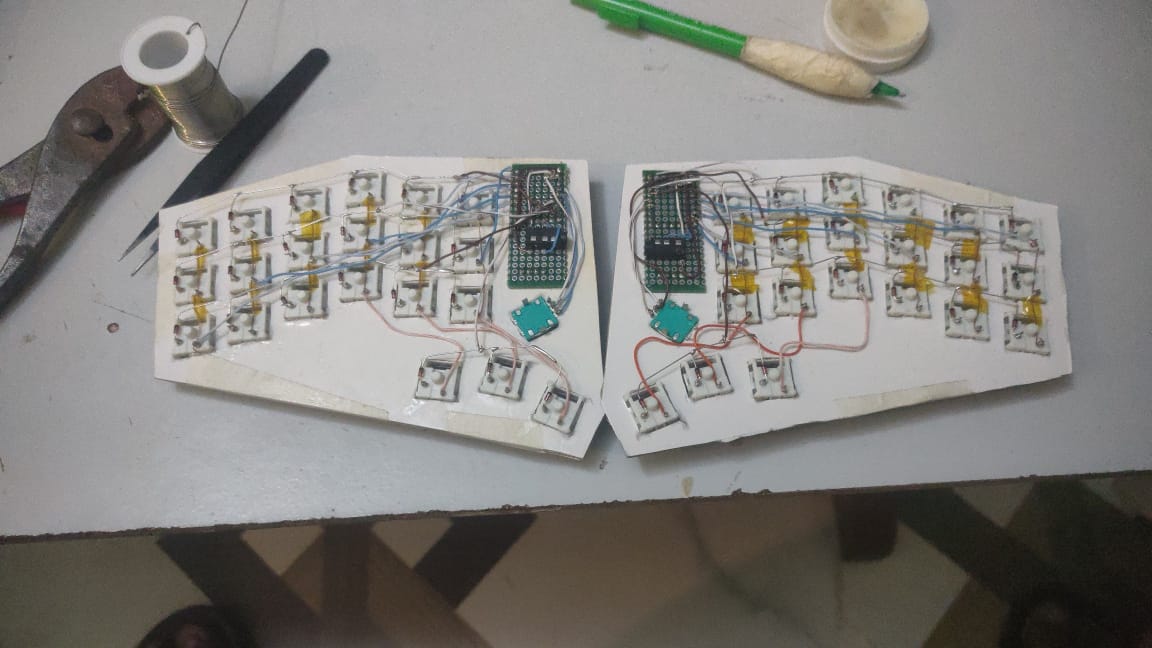
Diode Direction Wisdom: “Black side towards the Bus Line” for rows. Trust me, your matrix will thank you.
The matrix was a classic 6 columns by 4 rows. Simple, but effective.
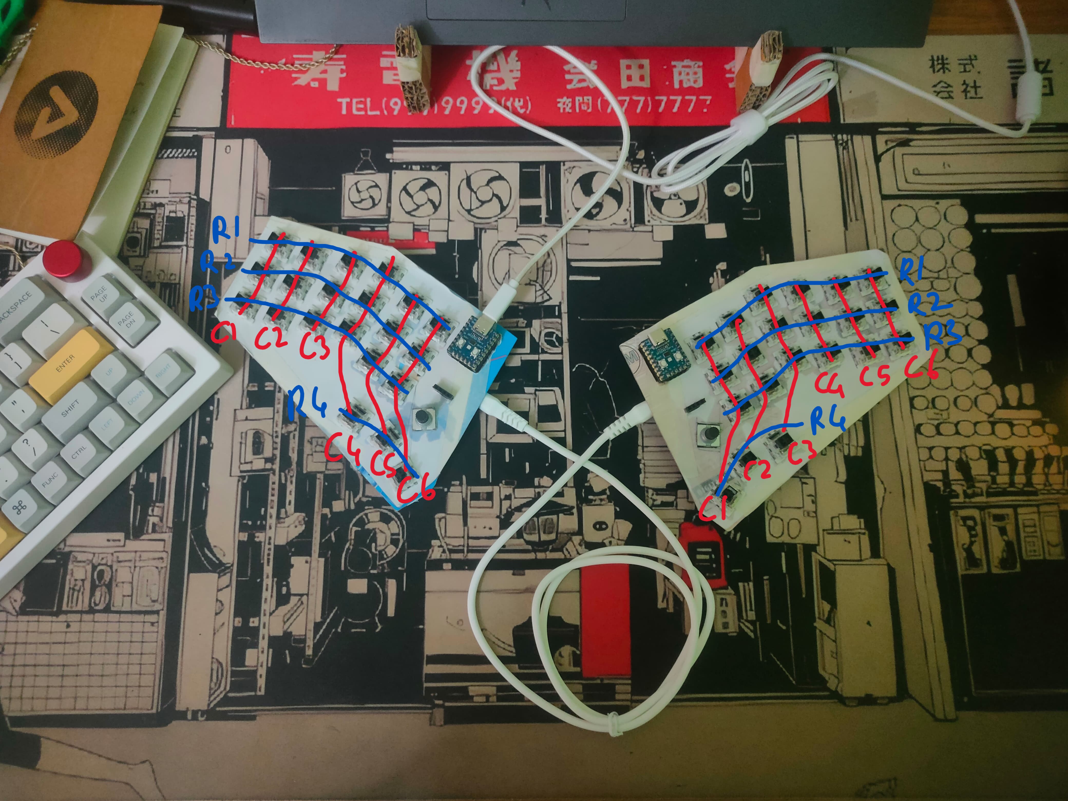
Matrix Mapping Note:
On my split keyboard, each side has a different physical matrix wiring and mapping. This means the left and right halves are not simple mirror images; their row/column wiring and key assignments differ, and the firmware keymap must match the actual hardware.Here’s a simplified version of my QMK keymap (C code) showing how both sides are mapped in the firmware:
const uint16_t PROGMEM keymaps[][MATRIX_ROWS][MATRIX_COLS] = {
    /* QWERTY
     * ┌───┬───┬───┬───┬───┬───┐       ┌───┬───┬───┬───┬───┬───┐
     * │Esc│ Q │ W │ E │ R │ T │       │ Y │ U │ I │ O │ P │Bsp│
     * ├───┼───┼───┼───┼───┼───┤       ├───┼───┼───┼───┼───┼───┤
     * │Tab│ A │ S │ D │ F │ G │       │ H │ J │ K │ L │ ; │ ' │
     * ├───┼───┼───┼───┼───┼───┤       ├───┼───┼───┼───┼───┼───┤
     * │Ctl│ Z │ X │ C │ V │ B │       │ N │ M │ , │ . │ / │Ent│
     * └───┴───┴───┴───┴───┴───┘       └───┴───┴───┴───┴───┴───┘
     *               ┌───┐                   ┌───┐
     *               │LOW├───┐           ┌───┤RAI│
     *               └───┤   ├───┐   ┌───┤   ├───┘
     *                   └───┤Sft│   │Sft├───┘
     *                       └───┘   └───┘
     */
    [_QWERTY] = LAYOUT_split_3x6_3(
        QK_GESC,  KC_Q,    KC_W,    KC_E,    KC_R,    KC_T,                KC_Y,    KC_U,    KC_I,    KC_O,    KC_P,    KC_BSPC,
        KC_TAB,  KC_A,    KC_S,    KC_D,    KC_F,    KC_G,                 KC_H,    KC_J,    KC_K,    KC_L,    KC_SCLN, KC_QUOT,
        KC_LCTL, KC_Z,    KC_X,    KC_C,    KC_V,    KC_B,                 KC_N,    KC_M,    KC_COMM, KC_DOT,  KC_SLSH,  KC_ENT,
                              MO(_LOWER), KC_SPC, KC_LSFT,           KC_RSFT ,KC_SPC,  MO(_RAISE)
    ),
    .
    .
Why does this matter?
If you wire the left and right halves differently (for example, the left half’s first column is physically wired to a different pin than the right half’s first column), you must ensure yourLAYOUT_split_3x6_3or custom layout macro matches your actual wiring.
Otherwise, keys will be scrambled or not work at all!Tip:
- Double-check your matrix assignments and test every key on both sides.
- If you use a custom matrix, you may need to define your own layout macro in
split.hor your keyboard’s header.- For more, see QMK’s split keyboard guide.
Firmware Development with QMK
With the hardware done, it was time to breathe life into my creation. I chose QMK over ZMK (wireless is cool, but I like my wires for now). The QMK docs and configurator were my guiding stars, but beware: some community files are ancient and will throw errors faster than you can say “deprecated syntax.” Reading the docs saved my bacon more than once.
Why Not ZMK? (For This Build)
ZMK is a fantastic firmware, especially for wireless split keyboards and low-power builds. I seriously considered it—wireless is tempting! But for this project, it just didn’t make sense:
- Wired Simplicity: I wanted a reliable, plug-and-play wired keyboard. ZMK shines with Bluetooth, but that adds complexity (batteries, charging, power management) I didn’t want for my daily driver.
- Hardware Support: My microcontroller was an RP2040 Zero. While ZMK does have some support for RP2040, QMK’s support is much more mature and stable for this chip—especially for wired splits. ZMK is still primarily focused on nRF chips (like the nice!nano), so I’d have to deal with more workarounds and less documentation for my hardware.
- Feature Maturity: QMK’s split keyboard support is mature and well-documented. ZMK’s split support is improving, but at the time of my build, it was still catching up—especially for wired splits and less-common MCUs.
- Community & Tools: QMK has a huge community, tons of guides, and the online Configurator. ZMK’s ecosystem is growing, but QMK’s resources made troubleshooting and customization much easier.
If I ever go wireless (hello, nice!nano), ZMK will be my first stop. But for this project, QMK was the clear winner for a wired, hassle-free split build with the RP2040 Zero.
Troubleshooting Steps
- Matrix Setup: My first attempt? A glorious mess. Fixed it after a deep dive into the docs.
- Layer Keys: Mapped them wrong, so my keyboard thought “A” was “Layer 2: Launch Missiles.” Oops. Fixed by remapping.
- Split Connection: My TRRS cable was a trickster—turns out the last ring and sleeve were connected. Switched from USART full duplex to half duplex in firmware. (Pro tip: QMK Serial Docs are your friend!)
// QMK config excerpt for split serial
#define SERIAL_USART_TX_PIN GP12
it uses USART Half Duplex by default but make sure to follow the docs for the setup.
- Thumb Cluster: The thumb cluster was all over the place. A few tweaks to the matrix, and order was restored.
- Encoder: Only the master side worked at first. Turns out, encoders are picky. The split encoder setup in the docs saved the day.
# config.h
#define ENCODER_A_PINS { GP5 }
#define ENCODER_B_PINS { GP4 }
#define ENCODER_RESOLUTIONS { 4 }

#define ENCODER_A_PINS_RIGHT { GP29 }
#define ENCODER_B_PINS_RIGHT { GP28 }
#define ENCODER_RESOLUTIONS_RIGHT { 4 }
Want to see the code and board structure? Check out my GitHub.
Debugging: Split Connection & Encoders
Testing both halves together was like herding cats. Thumb cluster mapping? Wrong. Encoder? Only one side spinning. Connection type? Mysteriously broken. But with every bug squashed, I felt like a keyboard sorcerer. Each fix was a mini victory dance.
Final Assembly & Keycaps
With the electronics humming and the firmware behaving, it was time for the finishing touch: keycaps! I borrowed some from my old keyboard (because who waits for shipping?), and finally, my split keyboard was ready for action. It looked awesome, felt even better, and—most importantly—actually worked.
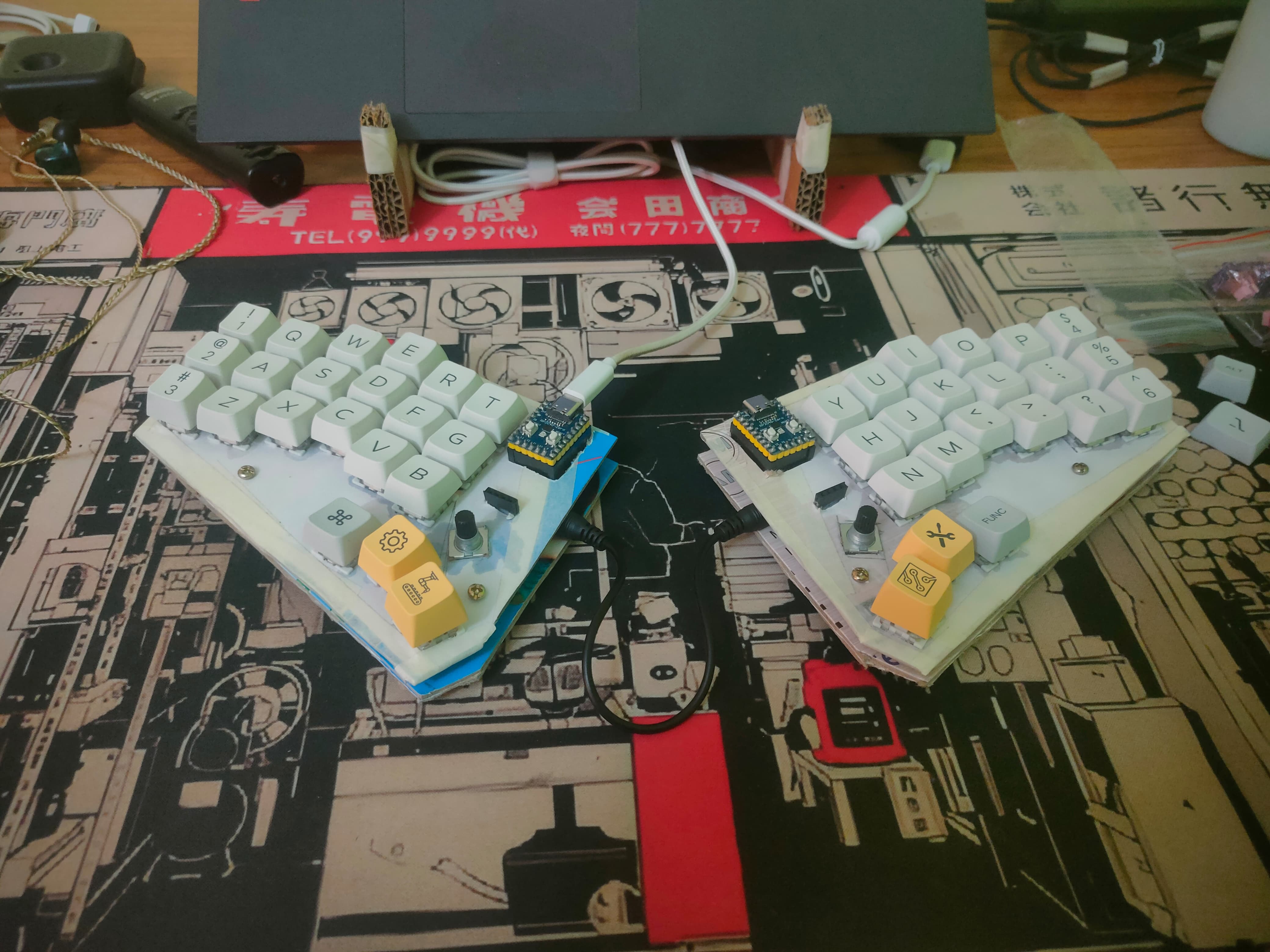
BTW, I will be getting keycaps in the near future.
What’s Next? OLEDs and PCBs
The journey doesn’t end here! Next up: adding OLED screens, designing a custom PCB, and maybe even 3D-printing a case. The possibilities are endless—and so are the late-night soldering sessions.
Useful Links & Resources
- Ergogen Unofficial Website
- Ergogen Docs
- Convertio DXF to SVG
- My Ergogen Files
- Robu.in
- QMK Docs
- QMK Configurator
- My QMK Code (Github)
Bill of Materials (BOM) & Affiliate Links
Below is a table of the main hardware components and equipment used for this build, along with approximate costs (as of June 2025) and affiliate links:
| Item | Approx. Cost (INR) | Affiliate Links |
|---|---|---|
| Key Switches (x60) | ₹435 | Cosmic Byte |
| Keycaps | ₹1100 | Curiosity Caps Non Affiliate Link |
| Rotary Encoder (EC11, x2) | ₹92 | Robu.in Non Affiliate Link |
| Diodes (1N4148, x50) | ₹115 | Quartz Components |
| Microcontroller | ₹580 | Quartz Components |
| TRRS Jack | ₹20 | Quartz Components |
| Female Pin Headers | ₹16 | Quartz Components |
| Soldering Iron | ₹400 | Quartz Components |
| Solder | ₹108 | Quartz Components |
| Flux | ₹18 | Quartz Components |
| Kapton Tape | ₹100 | Quartz Components |
| Tweezers | ₹185 | Quartz Components |
Total Cost (excluding equipment/tools):
If we sum up only the main hardware components (excluding the soldering iron, solder, flux, tweezers and Kapton tape), the total cost comes to:
- Key Switches: ₹435
- Keycaps: ₹1100
- Rotary Encoder (x2): ₹92
- Diodes: ₹115
- Microcontroller: ₹580
- TRRS Jack: ₹20
- Female Pin Headers: ₹16
Total = ₹2,358
This is the approximate cost for just the keyboard build itself (as of June 2025), not including tools or consumables.
Note: Prices are approximate and may vary.
Building a split keyboard from scratch is a wild ride—equal parts frustration, fun, and “aha!” moments. If you’re thinking of building your own, jump in! You’ll learn a ton, burn a few fingers, and end up with a keyboard that’s truly yours. Happy hacking! ⌨️ 🚀