
TL;DR:
This post walks through attacking a Raspberry Pi Pico W running a simple password-auth program using its SWD debug interface.
- Shows: Setting up a PicoProbe, dumping firmware over OpenOCD+GDB, and finding a plaintext password using
strings.- Covers: What SWD actually is, how Ghidra helps map the firmware, and three different ways to bypass authentication without ever typing the real password.
- Takeaway: A debug port left open and accessible is essentially a backdoor. Even if your code logic is perfect, an exposed SWD interface can hand an attacker full control of your device.
What is SWD and why should you care?
SWD, or Serial Wire Debug, is a two-wire debugging interface baked into virtually every ARM Cortex-M microcontroller ever made — and the RP2040 inside the Raspberry Pi Pico is no exception. It was developed by ARM as a slimmed-down alternative to JTAG, and it shows up on basically every modern embedded board you’ll work with: STM32s, nRF52s, RP2040s, you name it.
The interface uses just two signals — SWCLK (the clock line) and SWDIO (the bidirectional data line) — plus ground. That’s it. Two wires, and you have a direct window into the internals of the chip.
Compare that to JTAG, the older standard that needs at minimum four wires (TCK, TMS, TDI, TDO) plus ground. SWD achieves nearly everything JTAG does at half the pin count — which is exactly why it became the default choice for small embedded devices where every GPIO is precious.
So what can you actually do over SWD once you’re connected to a target?
- Flash firmware — write a new program directly into flash memory.
- Set breakpoints — pause execution at any instruction address, mid-run.
- Read and write memory — inspect RAM, flash, peripheral registers, anything in the address space.
- Dump the entire firmware — pull a full copy of flash to a file on your host machine.
- Control the CPU — halt, single-step, resume, or redirect execution anywhere you like.
For a developer, SWD is an incredibly powerful tool — real-time visibility into a running system without adding any overhead to the firmware itself. You just connect a probe, fire up OpenOCD and GDB, and you’re in.
For an attacker with physical access and the right hardware? It’s essentially an open door.
And that’s the crux of this post. We’re going to write a simple password-auth program, flash it to a Pico W, wire up a debug probe, dump the firmware, reverse engineer it in Ghidra, and then bypass the authentication three different ways using GDB — without ever typing the real password. Along the way, we’ll also stumble into the password the easy way first, because sometimes the most embarrassing vulnerability is the most obvious one.
Setting up the auth program
Installing the Pico SDK
We’re using the official VS Code extension from Raspberry Pi to set up the Pico SDK — it handles the toolchain, CMake config, and SDK download for you.
👉 Raspberry Pi Pico VS Code Extension
The target program
The firmware running on the target Pico W is a simple password-authentication loop. Nothing fancy — it prompts for a password over serial, checks it against a hardcoded value, and prints either “Access granted!” or “Access denied!”.
#include <stdio.h>
#include "pico/stdlib.h"
#include <string.h>

const char *PASSWORD = "bl0gpa55";

void access_granted() {
    printf("Access granted!\n");
}

void access_denied() {
    printf("Access denied!\n");
}

int check_auth(const char *input) {
    return strcmp(input, PASSWORD) == 0;
}

int main()
{
    stdio_init_all();

    char buf[32];
    while (1) {
        printf("Enter password: ");
        if (fgets(buf, sizeof(buf), stdin) == NULL) {
            printf("Error reading input\n");
            continue;
        }

        buf[strcspn(buf, "\r\n")] = 0;

        if (check_auth(buf)) {
            access_granted();
        } else {
            access_denied();
        }
    }
}
A couple of things worth noting about the code:
Why fgets and not scanf("%31s", buf)?scanf with %s stops reading at the first whitespace — which means a password like "my password" would silently be read as just "my". Worse, if you forget the width specifier it will happily overflow the buffer. fgets reads a full line including spaces, and the length limit is enforced by the buffer size passed as the second argument. It’s the safer, more predictable choice for line-oriented input.
The --omap crlf flag in picocom:
When you run picocom -b 115200 --omap crlf /dev/ttyACM0 to talk to the Pico over USB serial, the --omap crlf option maps outgoing newlines (\n) to carriage-return + newline (\r\n). This matters because fgets on the Pico side waits for a newline to know when the user finished typing. Without the mapping, your Enter key in picocom might only send \n — which the serial input layer may or may not interpret as a line terminator depending on the platform. Sending \r\n keeps things reliable.
Flashing the program
- Hold down BOOTSEL on the Pico and plug it in to enter bootloader mode.
- Build the project — you’ll get a
.uf2file in the build directory. - Copy the
.uf2into theRPI-RP2mass storage drive that appears. - The Pico reboots automatically and starts running the firmware.
Verify it’s working with:
picocom -b 115200 --omap crlf /dev/ttyACM0
You should see the Enter password: prompt over serial.
The debug probe: PicoProbe
Why my CMSIS-DAP stopped working
Here’s where things got annoying before they got interesting.
My original debug probe was a Muselab CMSIS-DAP v2.3 — a budget adapter I’d been using happily for a while. Plugged it in, pointed OpenOCD at the RP2040, and… nothing. Timeouts, failed connects, OpenOCD just refusing to cooperate. Great start.
After some digging, the culprit turned out to be the RP2040’s dual-core architecture. Unlike most Cortex-M chips with a single core, the RP2040 has two Cortex-M0+ cores running independently — core0 and core1. When a debug adapter connects over SWD, it has to properly handle halting both cores in a coordinated way. Older or budget CMSIS-DAP firmware often just doesn’t implement this correctly — the halt handshake either fails silently, times out, or leaves one core in a state that confuses OpenOCD entirely.
The Muselab v2.3 firmware predates solid dual-core SWD support, so the RP2040’s dual-core nature just completely outpaced what it could handle. No amount of config tweaking was going to fix outdated firmware on a closed adapter.
The fix? Stop fighting it and turn a spare Pico into a debug probe instead.
Flashing PicoProbe (debugprobe)
The Raspberry Pi foundation maintains debugprobe — an open-source firmware that turns any Pi Pico into a fully capable CMSIS-DAP adapter with proper RP2040 dual-core support.
Flash it the same way as any Pico firmware — hold BOOTSEL, plug in, drop the .uf2 into the drive. That Pico is now your probe.
PicoProbe pinout
From the debugprobe board config:
| Signal | GPIO |
|---|---|
| SWCLK | GP2 |
| SWDIO | GP3 |
| UART TX (to target RX) | GP4 |
| UART RX (from target TX) | GP5 |
Wiring the probe to the target Pico W
| PicoProbe (Probe) | Target Pico W | |
|---|---|---|
| GP2 | ↔ | SWCLK (debug port) |
| GP3 | ↔ | SWDIO (debug port) |
| GP4 (UART TX) | ↔ | GP1 (RX) |
| GP5 (UART RX) | ↔ | GP0 (TX) |
| GND | ↔ | GND |
| VBUS | ↔ | VSYS |
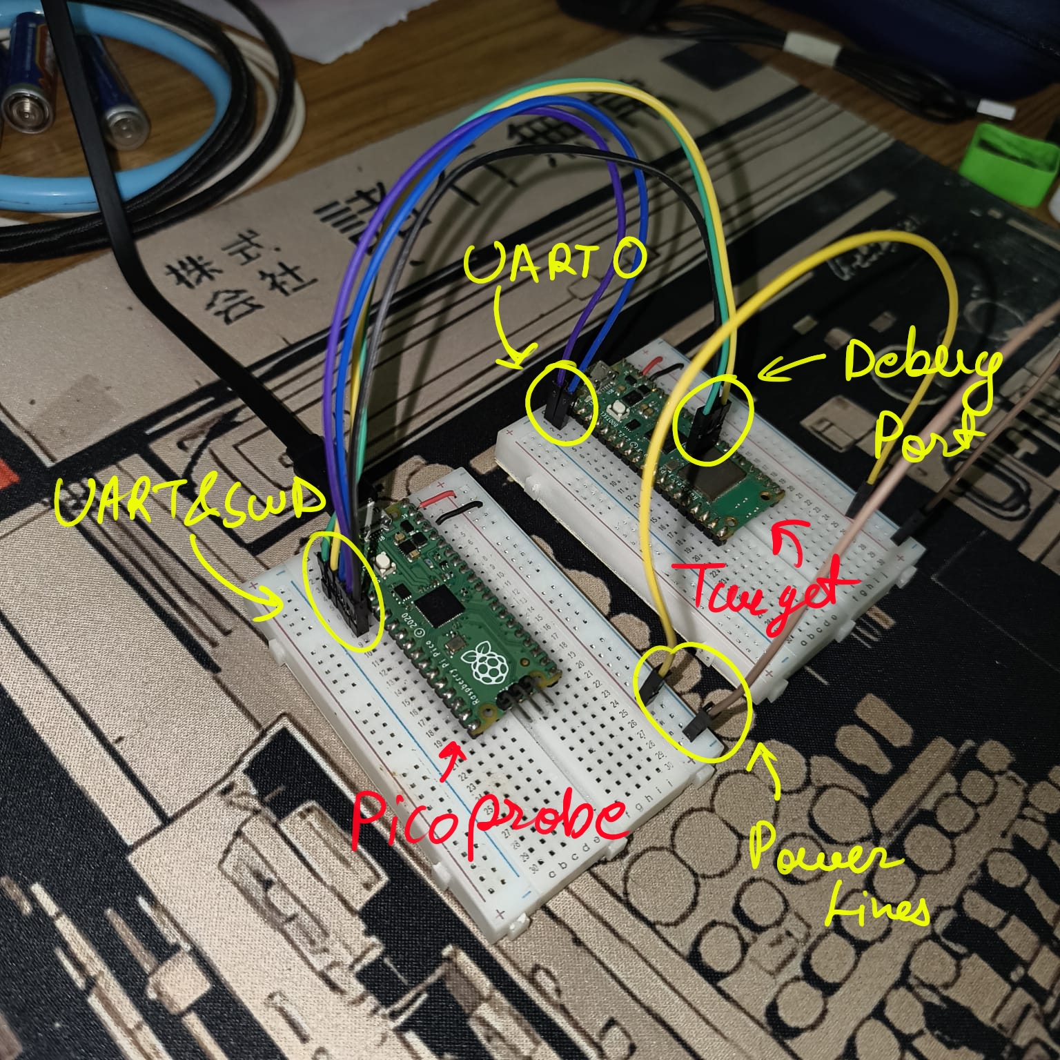
A quick note on VBUS vs VSYS:
On the Pico, VBUS is the raw 5 V line coming directly from the USB connector — it’s what the USB host provides. VSYS is the main system power rail, which sits at around 3.7–5.5 V and feeds the onboard 3.3 V regulator. When you power the target Pico from the probe’s VBUS and connect it to the target’s VSYS, you’re bypassing the target’s USB port and feeding it power directly through the system rail — this is the right way to power a secondary board without needing a second USB cable, and it keeps both boards at the same effective supply level.
Dumping the firmware
Alright — the target is wired up, the probe is flashed, everything is connected. This is where the fun begins.
Up to this point it’s all been setup. A bit of soldering, some firmware flashing, the usual embedded faff. But now we have a working SWD link to a live Pico W running a password-protected program, and we’re about to start pulling it apart. The goal for this section: get a full copy of the firmware off the device, just from those two debug wires.
Setting up OpenOCD and GDB
Open two terminals.
Terminal 1 — start OpenOCD:
openocd -f interface/cmsis-dap.cfg -f target/rp2040.cfg
Terminal 2 — connect GDB:
gdb-multiarch
Inside GDB:
target remote localhost:3333
monitor reset halt
Dumping flash to a file
The RP2040 maps its flash starting at address 0x10000000. The Pico has 2 MB of flash, so we dump 0x200000 bytes from that base address.
Before running the dump, increase the GDB remote timeout — otherwise OpenOCD will give up mid-transfer on a 2 MB read:
set remotetimeout 600
dump binary memory pico_fw.bin 0x10000000 0x10200000
Verify the dump came out the right size:
taklaman@ubuntu:~/Downloads$ ls -lh pico_fw.bin
-rw-rw-r-- 1 taklaman taklaman 2.0M May  4 23:01 pico_fw.bin
2.0 MB — exactly what we expected.
Note on the base address: The RP2040’s memory map places external flash at
0x10000000. If you’re working with a different microcontroller, always look up its memory map first — dumping from the wrong address will give you garbage or nothing useful. A good reference for the Pico specifically is Pete Warden’s memory layout breakdown.
Static analysis: strings and Ghidra
What strings reveals
strings scans a binary for sequences of printable characters long enough to be meaningful (typically 4+ characters). On a firmware binary, it’s one of the first things you run because firmware often contains:
- Hardcoded credentials — passwords, API keys, tokens stored as plain strings.
- Debug/prompt strings —
"Enter password:","Access granted!", error messages. - Version and build info — compiler version strings, build timestamps, git hashes.
- URLs and endpoints — Wi-Fi SSIDs, API base URLs, cloud endpoints.
- Symbol names — if the firmware wasn’t stripped, function and variable names leak the program’s structure.
- Cryptographic material — sometimes base64-encoded keys or salts show up in plain sight.
Running it on our dump:
strings pico_fw.bin | grep -i "pass\|auth\|grant\|deny\|enter"
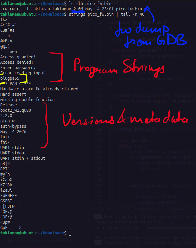
There it is — bl0gpa55 sitting in plain text in the firmware. The prompt strings, the “Access granted!” and “Access denied!” messages, all visible. The password wasn’t hashed, wasn’t obfuscated, not even stored in a separate region — just a const char* in flash, readable by anyone with a debug interface and 30 seconds.
This is the most common credential exposure issue in embedded development. The developer (me, in this case!) was thinking about runtime behaviour — input handling, buffer safety — but wasn’t thinking about what ends up sitting in flash in plaintext.
Let’s use it
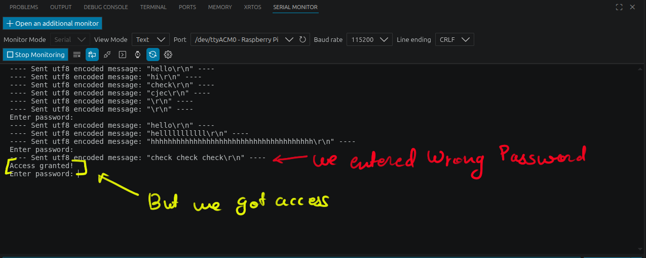
Before we go any further — we have the password, so let’s actually use it. Pull up picocom, type bl0gpa55, and:
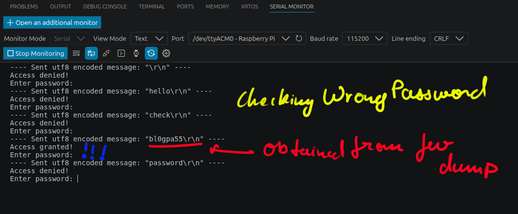
There we go. Access granted, and we never had to look at a single line of source code. We just asked the firmware nicely, and it told us everything.
That alone is a serious finding — and in a lot of real engagements, that’d be enough to write the report. But we’re not done. We want to understand how this auth works at the instruction level, and then bypass it without the password at all.
Reversing with Ghidra
Load pico_fw.bin into Ghidra, set the language to ARM Cortex-M (LE, 32-bit, Thumb), and set the base address to 0x10000000 to match the RP2040 memory map.
Open the Defined Strings window (Window → Defined Strings). Ghidra lists every string it found in the binary — you’ll immediately spot your prompt strings: "Enter password: ", "Access granted!", "Access denied!", and more. What’s useful here is the XREF column in the Listing window — it shows every location in the disassembly that references each string.
In the screenshot below, look at s_Access_denied!_100051d8 — it has two XREFs: FUN_100002d4:100002f8 and FUN_100002d4:10000334. Both point back into the same function, FUN_100002d4, which is our main() auth loop. The "Enter password: " string’s XREF points to FUN_100002d4:100002fe — same function, the printf call at the top of the loop. Cross-referencing "Access granted!" takes you directly to the branch that calls access_granted().
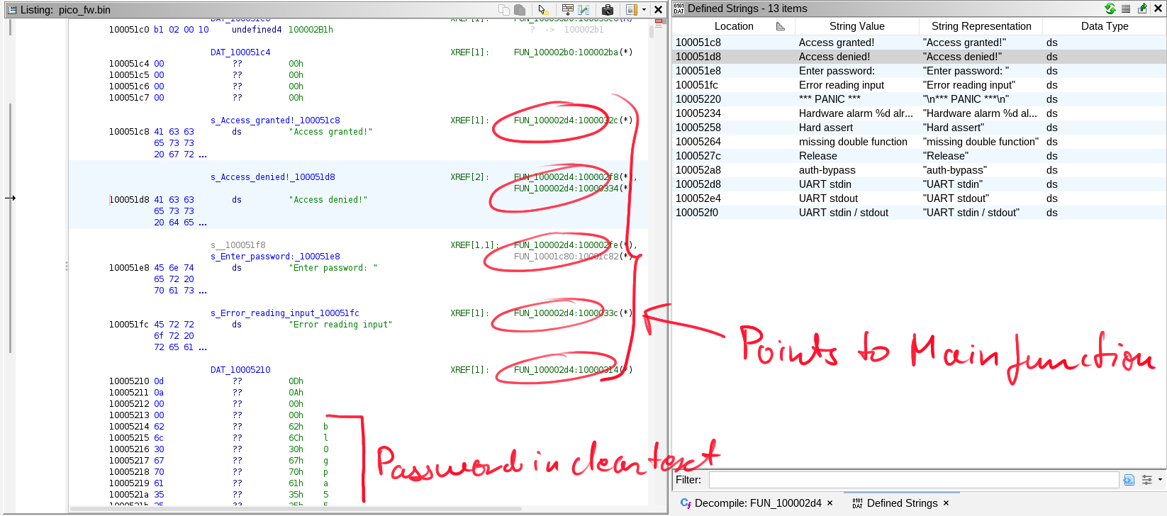
From there you can read the decompiled output, see the strcmp call, and identify the exact instruction addresses where the comparison result determines which branch is taken. That’s our target for GDB.
Taking control: bypassing auth with GDB
We know the memory layout, the function logic, and the address of the branch that decides whether to call access_granted() or access_denied(). Now we use GDB to manipulate the running program in real time.
Start OpenOCD and GDB the same way as before. Connect to the target, then pick your approach:
Option A — Patch R0 after strcmp
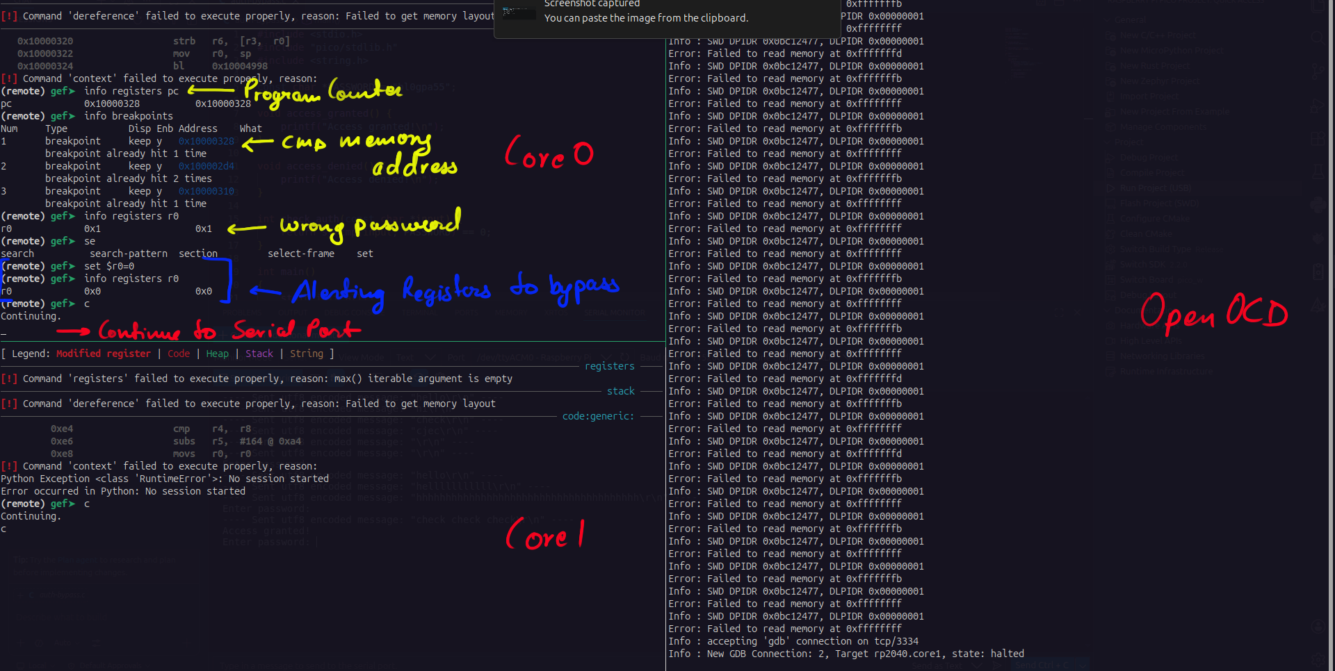
After strcmp returns, its result is in register R0. Zero means equal (match), non-zero means no match. We set a breakpoint right after the call returns, let it fire when a wrong password is entered, then overwrite R0.
break *0x10000328
continue
# type wrong password in picocom
# GDB halts here after strcmp returns
info registers r0
# r0 is non-zero — access would be denied
set $r0 = 0
continue
# → Access granted!
Option B — Jump PC directly to the granted path
Instead of fixing the return value, we skip straight to access_granted() by redirecting the program counter.
break *0x10000328
continue
# type wrong password
set $pc = 0x1000032c
continue
# → Access granted!
Option C — Patch the branch instruction (NOP it out)
The most permanent runtime patch: overwrite the conditional branch instruction with a NOP so the “denied” path is never taken, regardless of what strcmp returns.
ARM Thumb NOP is 0x46C0.
break *0x1000032a
continue
# bne (branch-if-not-equal) sits at 0x1000032a
set {short}0x1000032a = 0x46c0
continue
# → Access granted!
We went with Option A for the demo.
Why you need to handle both cores
One thing that tripped us up: after halting core0 and patching the register, execution didn’t resume cleanly until we also continued core1.
The RP2040 has two independent Cortex-M0+ cores. When OpenOCD halts the chip over SWD, it halts both cores. If you only resume core0, core1 stays paused — and depending on what the SDK’s runtime or any second-core task is doing, this can leave the program in a stuck state. The Pico SDK’s multicore subsystem uses core1 for its own housekeeping even if you haven’t explicitly launched anything on it. Both cores need to be continued for the system to run normally after a debug halt.
Findings and takeaways
Here’s the full picture of what this exercise surfaced:
Vulnerability 1: Plaintext password in flash
CWE-259 — Use of Hard-coded Password
CWE-312 — Cleartext Storage of Sensitive Information
Severity: Critical
The password was stored as a const char* — a literal string baked directly into the firmware binary. Anyone who can dump flash (via SWD, JTAG, or even desoldering the flash chip) gets the password for free. No bruteforcing, no side-channel analysis, just strings.
CWE-259 covers the practice of embedding credentials directly in code or firmware — the moment you write const char *PASSWORD = "bl0gpa55", you’ve committed this one. CWE-312 covers the storage side: the secret isn’t just hardcoded, it’s sitting in flash completely in the clear, with no encryption or obfuscation of any kind.
Fix: Never store credentials in plaintext in firmware. At minimum, store a hash and compare against that. Better still, use a proper key derivation function and avoid embedding secrets in the binary at all — use provisioning flows that write credentials to protected storage at manufacturing time.
Vulnerability 2: Exposed SWD debug interface
CWE-1244 — Internal Asset Exposed to Unsafe Debug Access Level or State
CWE-1191 — On-Chip Debug and Test Interface With Improper Access Control
Severity: Critical
This is the root issue — everything else in this post flows from it. The SWD debug port was left fully active and accessible on the production-equivalent firmware. With physical access and a ~$10 probe, an attacker can:
- Dump the full firmware.
- Set breakpoints anywhere.
- Read and write any memory or register.
- Redirect execution to any address.
CWE-1244 specifically calls out the scenario where an internal asset (here, the CPU and its memory) is reachable through a debug interface that hasn’t been restricted for deployment. CWE-1191 is the more specific embedded variant — it covers debug and test interfaces like JTAG and SWD where access control hasn’t been implemented or enforced. Both apply cleanly here.
Fix: Production firmware should disable or lock the SWD interface. The RP2040 supports this via the ACCESSCTRL and SYSCONFIG registers, and you can configure the debug access level before shipping. For higher-security applications, look at disabling SWD entirely in the boot ROM configuration.
Vulnerability 3: No runtime tamper detection
CWE-1320 — Improper Protection for Outbound Error Messages and Alert Signals
CWE-693 — Protection Mechanism Failure
Severity: High
Our patches were completely invisible to the running program. We overwrote a register value mid-execution and the firmware had no idea — there was no watchdog checking register integrity, no code signing verification, no secure boot, nothing to detect that the program flow had been manipulated from the outside.
CWE-693 is the broad umbrella here — a protection mechanism (the authentication check) existed, but the overall system failed to protect it from being subverted by an external actor with debug access. CWE-1320 touches on the lack of any signalling or detection when the device’s integrity is compromised — a hardened system would at minimum detect the debug halt and trigger a response.
Fix: Enable secure boot where the hardware supports it. The RP2350 (Pico 2) introduced signed boot images and a One-Time Programmable (OTP) region for locking down debug access — worth exploring if security is a concern. Even short of that, a production device should treat unexpected halts or resets as a tamper event and respond accordingly.
The bigger picture
Debug interfaces like SWD exist for a very good reason — they make embedded development vastly easier. But a tool that gives developers full control over a device gives an attacker full control too, if it’s left open.
This isn’t a theoretical concern. IoT products shipped with active JTAG/SWD ports have been exploited in the real world — everything from consumer routers to industrial controllers. The attack is straightforward enough that it’s a standard step in any embedded security assessment.
The lesson isn’t “never use SWD” — it’s “know what your debug interface exposes, and lock it down before you ship.” Treat it the same way you’d treat a physical serial console or an open admin interface: fine for development, dangerous in production.
Relevant Links
- Raspberry Pi Pico VS Code Extension — SDK setup via VS Code.
- debugprobe firmware (v2.3.0) — PicoProbe
.uf2used in this post. - debugprobe board config / pinout — Source of the GPIO assignments.
- RP2040 Memory Layout — Pete Warden — Clear breakdown of where flash, RAM, and peripherals live in the RP2040 address space.
- Ghidra — The NSA’s open-source reverse engineering suite used for firmware analysis.
- OpenOCD — Open On-Chip Debugger, used to bridge GDB to the target over SWD.