
This blog post covers my research and hardware reverse engineering of the TP-Link Tapo C200 V3.28 IN, a widely used home security camera. I will discuss the device’s setup, hardware features, and the process of analyzing its internal components from a security research perspective.
Target
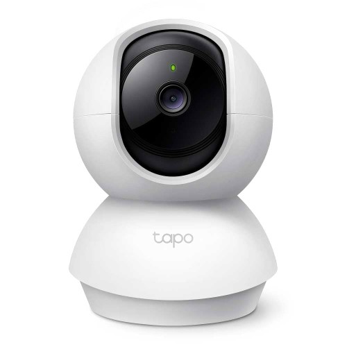
Before getting into the hardware, I have already done the setup of the Camera with the App
Hardware Exploration
Hardware Used
For this research and teardown, I used the following hardware tools and equipment:
- TP-Link Tapo C200 V3.28 IN – The main subject of the analysis, a popular home security camera.
- Multimeter – Essential for probing connections, checking voltages, and verifying continuity on the PCB.
- Screwdriver – Used to carefully open the camera casing without damaging the internals.
- Jumper Wires – For making temporary connections to test pads and UART points during analysis.
- Soldering Iron – Required for attaching jumper wires to small pads and test points on the board.
- FTDI232R – USB-to-serial adapter, used to interface with the camera’s UART for serial console access.
- CH341A – USB programmer, useful for reading and writing SPI flash memory chips.
These tools enabled a thorough hardware exploration and allowed for safe disassembly, probing, and interfacing with the camera’s internal components.
Label of the Camera (on the Back side of the Camera)
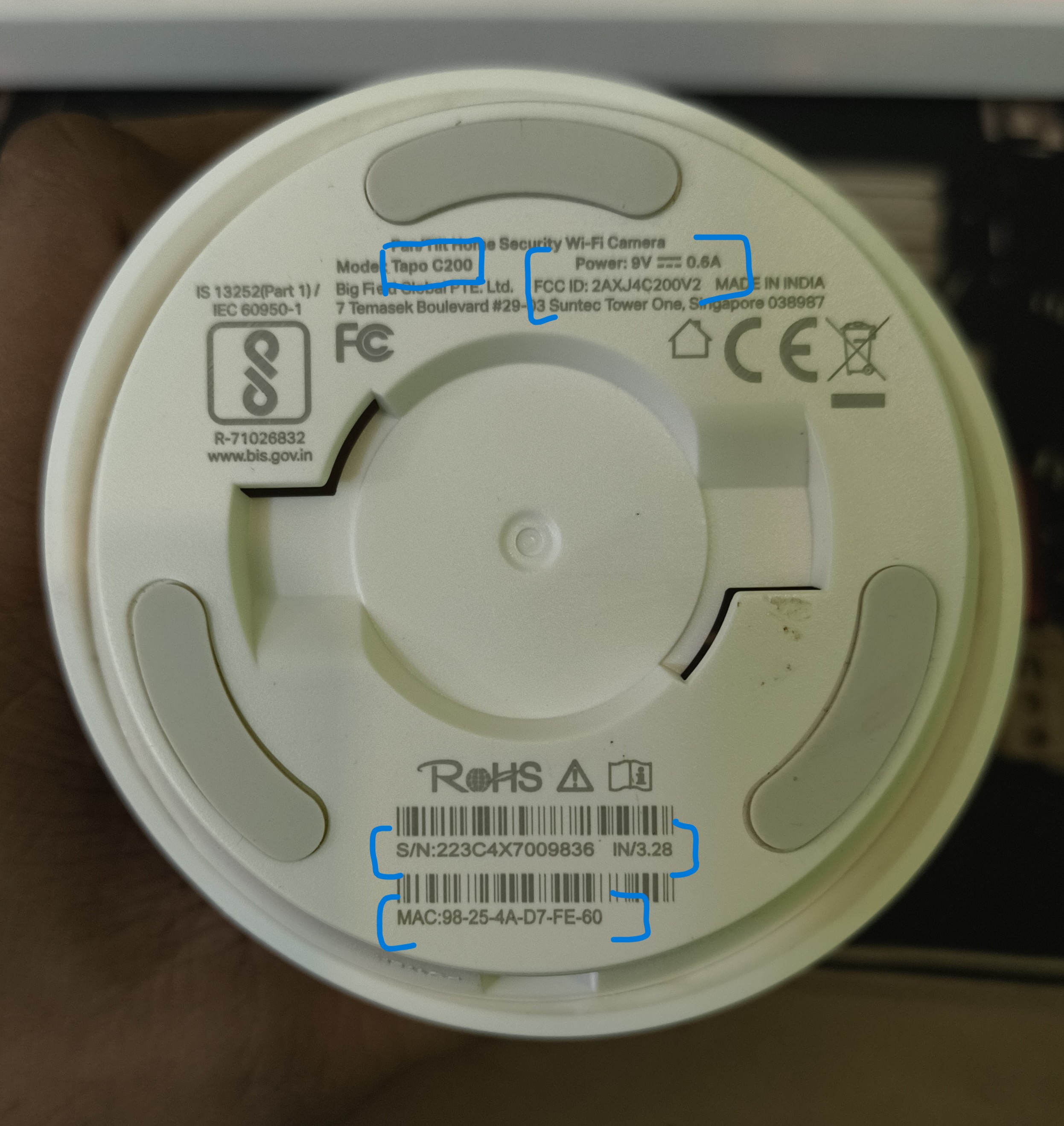
Examining the label on the back of the camera provides several important hardware and regulatory details about the device:
- FCCID: 2AXJ4C200V2 - This is the unique identifier assigned by the FCC, which can be used to look up regulatory filings, internal photos, and technical documentation for the device.
- MAC Address: 98:25:4A:D7:FE:60 - The MAC address is unique to this unit and is used for network identification.
- Power Requirements: 9V 0.6A - Indicates the camera requires a 9-volt power supply with a current draw of 0.6 amps, which is useful for selecting compatible adapters or for bench testing.
- Serial Number: The serial number is specific to each device and can be used for warranty, support, or tracking purposes.
These details are not only useful for identification and regulatory research, but also help guide the hardware analysis and teardown process.
Looking up the FCC ID reveals teardown images, PCB layout, and details of major components.
With the basic details in hand, I proceeded to disassemble the camera to examine its internal components and better understand the hardware inside.
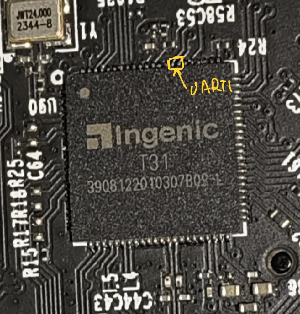
Interestingly, while the FCC filing shows a Realtek processor, this unit instead contains an Ingenic T31 SoC. Datasheet reference: Ingenic T31.
Processor
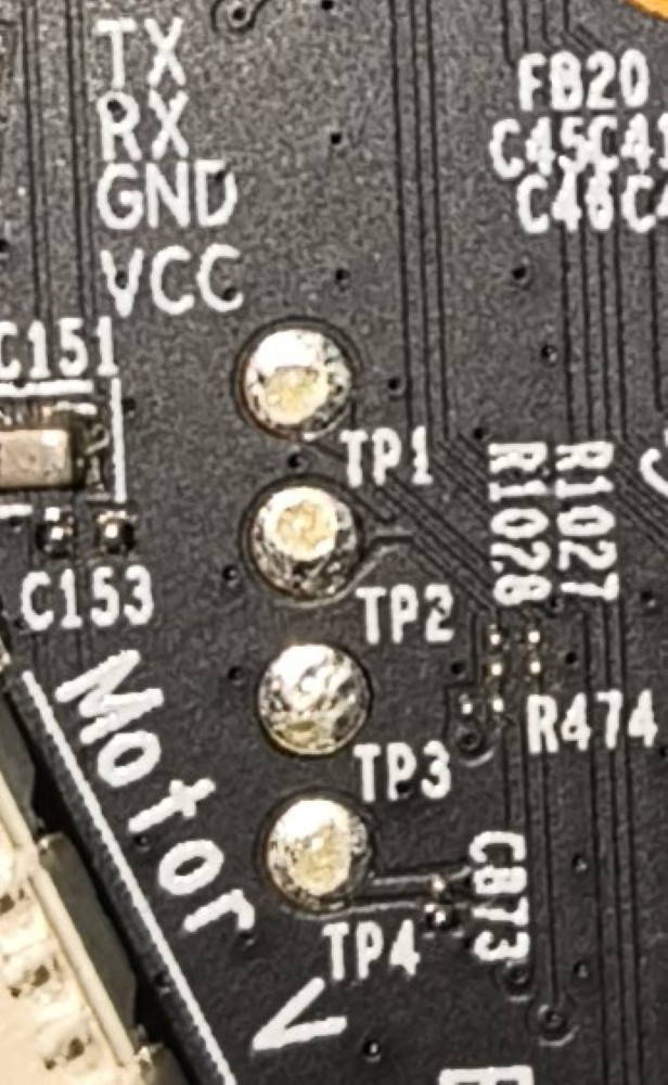
UART Pads
Wifi Chip
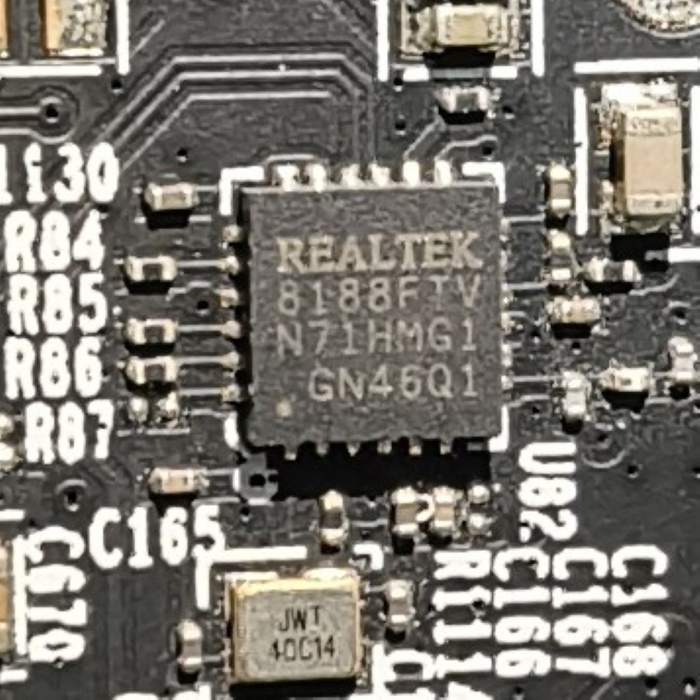
UART and Flash Analysis
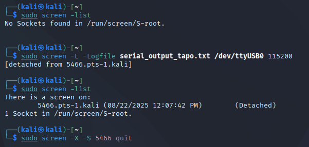
Initially, I soldered jumper to the UART pad and pulled up screen and got to I/O on the terminal, and then I noticed the UART pads weren’t directly connected.
Took a Multimeter and started probing the pads and the small solder points in contiunity mode and found the following:
- Top solder points connect to TX/RX
- Ground confirmed via chassis screw
- Lower solder points connect to UART1 of the Ingenic T31 (Pin 73 = RX, Pin 74 = TX)
UART Pads Details
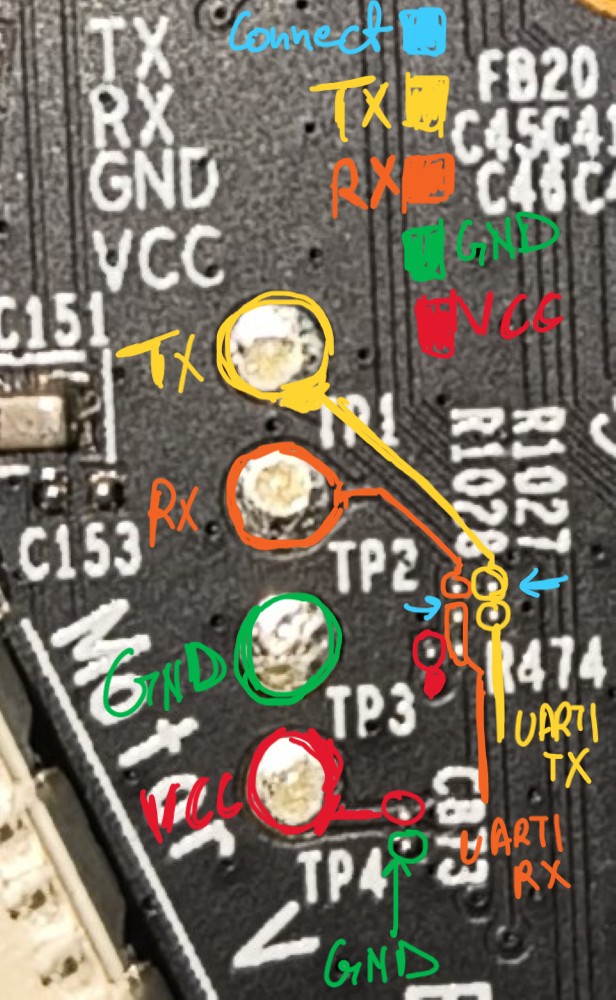
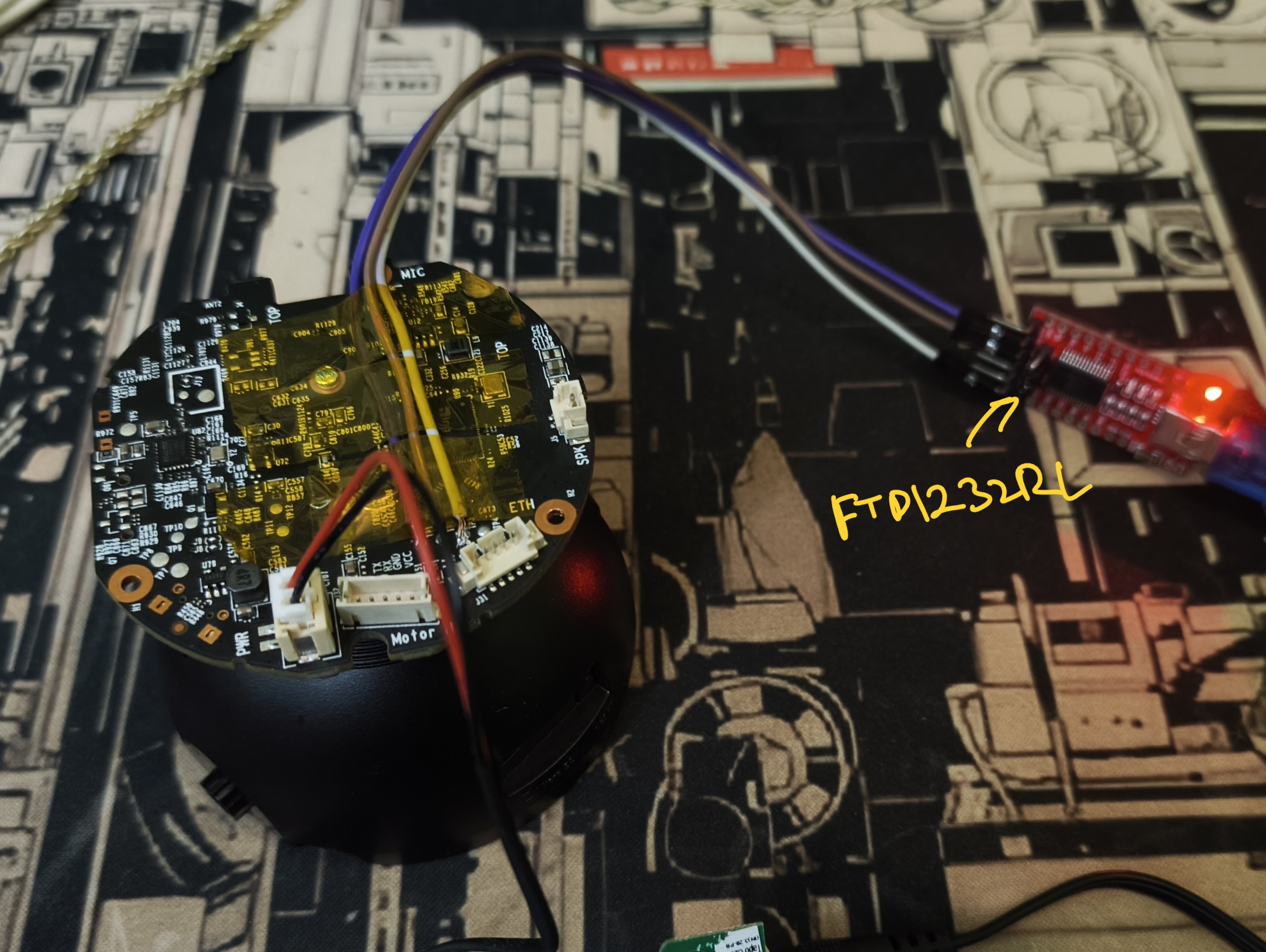
To establish UART communication on Linux, I only needed to connect the GND, TX, and RX lines—so I left the VCC line untested. After identifying the correct pads, I soldered jumper wires to the test points, making it easy to interface with the camera’s serial console.
Tried the screen again, GOT THE UART debug messages and the I/O worked fine. Tried to check the login, but was getting Login incorrect just after giving the username {Spoiler: The login is disabled on telemetry and the UART is using the same script}.
UART Connection
UART_screen
To gain deeper insight into the system, the next step was to access the camera’s filesystem. For this, I used a CH341A programmer along with flashrom to dump the flash memory. You can do this either by desoldering the chip (off-chip) or, more conveniently, by using a SOIC clip to read the flash in-circuit. I opted for the clip method—it’s much less invasive and allows the device to remain fully functional afterward.
SPI Flash
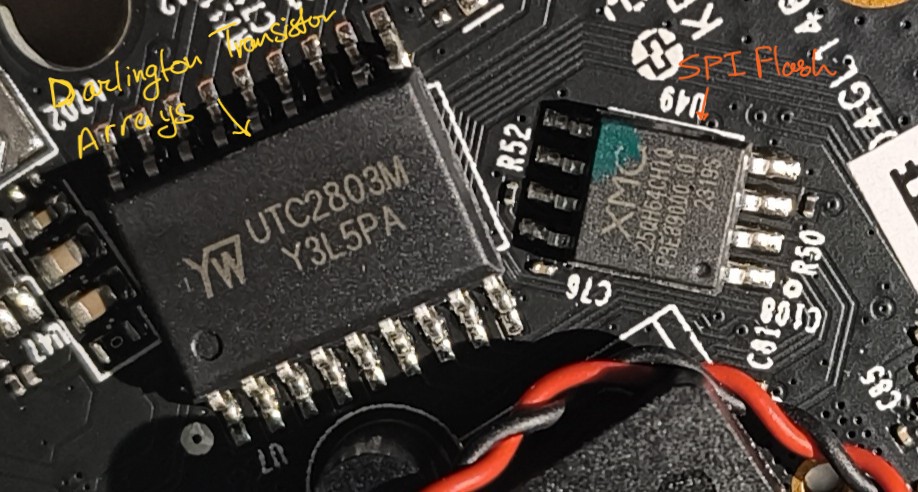
Dumping Flash
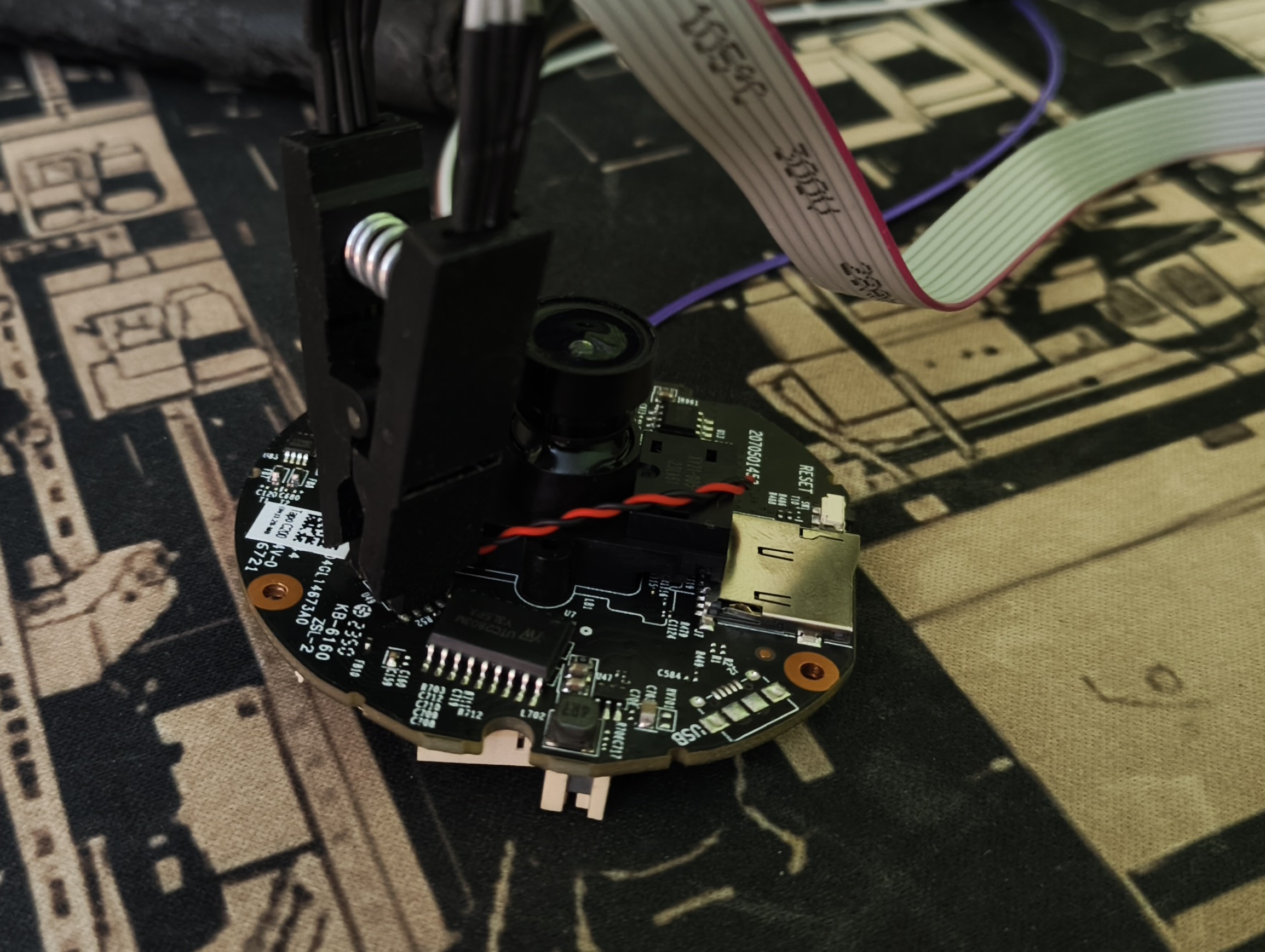
flashrom_flash read
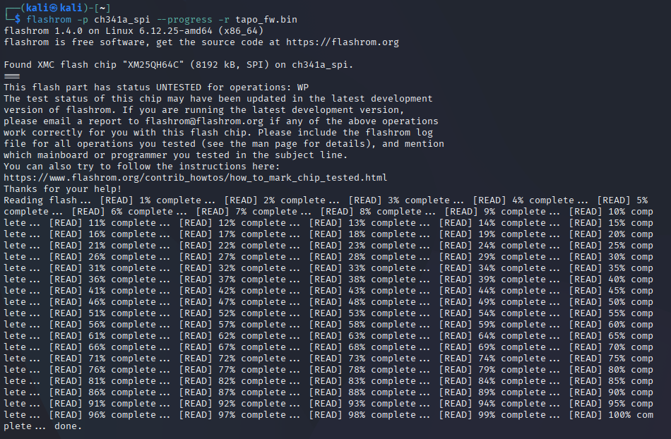
With the flash dump in hand, it was time to analyze the filesystem. Running binwalk on the firmware image revealed the internal file structure and partition layout.
Binwalk Analysis
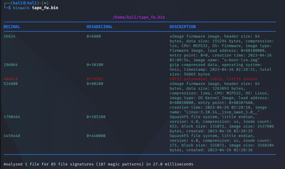
While reviewing the UART debug messages, I discovered a particularly interesting detail: the complete partition layout of the flash memory is revealed.
[    0.588100] Creating 10 MTD partitions on "jz_sfc":
[    0.593160] 0x000000000000-0x00000002d800 : "factory_boot"
[    0.598836] mtd: partition "factory_boot" doesn't end on an erase block -- force read-only
[    0.607880] 0x00000002d800-0x000000030000 : "factory_info"
[    0.613598] mtd: partition "factory_info" doesn't start on an erase block boundary -- force read-only
[    0.623581] 0x000000030000-0x000000040000 : "art"
[    0.628877] 0x000000040000-0x000000060000 : "config"
[    0.634516] 0x000000060000-0x000000080000 : "normal_boot"
[    0.640564] 0x000000080000-0x0000001b5200 : "kernel"
[    0.645788] mtd: partition "kernel" doesn't end on an erase block -- force read-only
[    0.654276] 0x0000001b5200-0x000000440000 : "rootfs"
[    0.659415] mtd: partition "rootfs" doesn't start on an erase block boundary -- force read-only
[    0.668908] 0x000000440000-0x000000fffe00 : "rootfs_data"
[    0.674532] mtd: partition "rootfs_data" doesn't end on an erase block -- force read-only
[    0.683454] 0x000000fffe00-0x000001000000 : "verify"
[    0.688593] mtd: partition "verify" doesn't start on an erase block boundary -- force read-only
[    0.698073] 0x000000080000-0x000001000000 : "firmware"
Curious to explore the contents of the config partition, I attempted to access its data—only to discover that the entire partition was encrypted.
Config Extract

While exploring the extracted filesystem, I came across the passwd file containing a password hash. The first thing I usually do in this situation is to search online to see if anyone has already cracked the hash—especially since this product has multiple hardware and firmware revisions, and password hashes often get shared in public forums. During my search, I found a promising comment from a user named DrmnSamoLiu on a relevant GitHub issue page, which seemed like it could lead to a breakthrough.
Github Issue Image
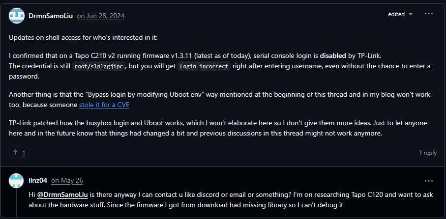
To verify the password, I used OpenSSL to check the hash (including the salt) against the one stored in the passwd file. The result matched exactly, confirming that we had successfully identified the correct password hash.
Password Check

Despite having the correct password, attempting to log in again still resulted in an “incorrect login” error.
At this point, I shifted my focus back to the encryption mechanism protecting the Config partition. Digging through the system’s library files and initialization scripts, I noticed that a utility called uc_convert was frequently invoked for handling data operations. Curious about its role, I explored the /usr/lib/opkg directory and uncovered more information about uc_convert and its associated dependencies.
UC_convert
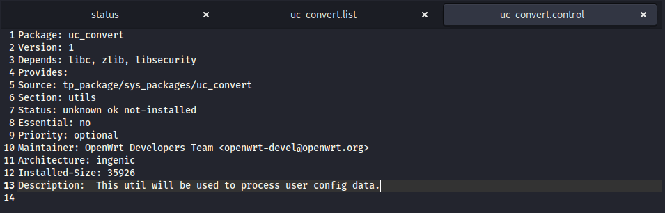
The uc_convert utility relies on three primary components:
- /usr/lib/libuc_convert.so
- /bin/uc_convert
- /lib/preinit/99_10_read_uc_data
Dependency of uc_convert

I also attempted to reverse engineer the relevant files to locate the encryption key, but so far I haven’t been able to pinpoint its address—mainly because I haven’t dedicated enough time to a thorough analysis yet.
UBOOT Exploit and Root Access
While exploring ways to access the system, I learned that on U-Boot devices, TP-Link specifically uses the slp command to trigger the U-Boot prompt during boot. This allows for low-level interaction with the device and opens up further possibilities for analysis.
Inspecting the U-Boot environment reveals several important parameters, such as:
baudrate: 115200 (serial communication speed)bootargs: kernel boot arguments (we’ll modify this to gain a root console)bootcmd: the default boot command …and many other settings, though we’ll focus on the most relevant ones for our purposes.
UBoot bootargs
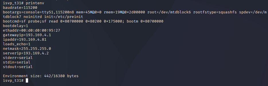
By modifying the bootargs parameter, we can bypass the preinit process and gain direct access to a root shell on the console. To achieve this, use the following command in the U-Boot prompt:
setenv bootargs console=ttyS1,115200n8 mem=45M@0x0 rmem=19M@0x2d00000 root=/dev/mtdblock6 rootfstype=squashfs spdev=/dev/mtdblock7 noinitrd init=/bin/sh
boot
After rebooting, we were greeted with a root shell on the console, granting us full administrative access to the device.
Root Access
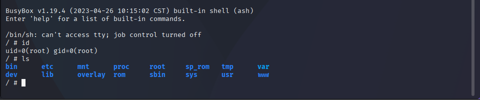
Root env
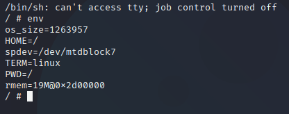
With full root access, I explored the file system and decided to observe uc_convert in action to better understand how it operates within the device environment.
commands to run to make uc_convert to run:
mount -t proc none /proc
mount -t tmpfs -o mode=0755 tmpfs /dev
mount -t tmpfs -o size=20633600,nosuid,nodev,mode=1777 tmpfs /tmp
mknod /dev/slp_flash_chrdev c 222 0
ls /tmp
uc_convert -t O
Next, by navigating to /tmp/etc, we can observe that various configuration files are generated and stored there.
Files in /tmp/etc
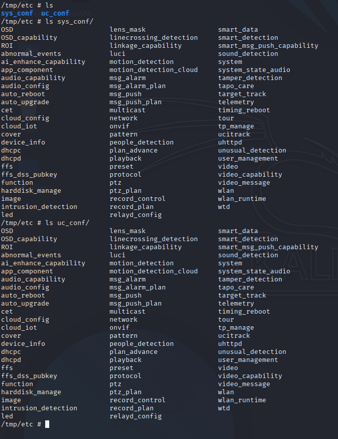
Findings
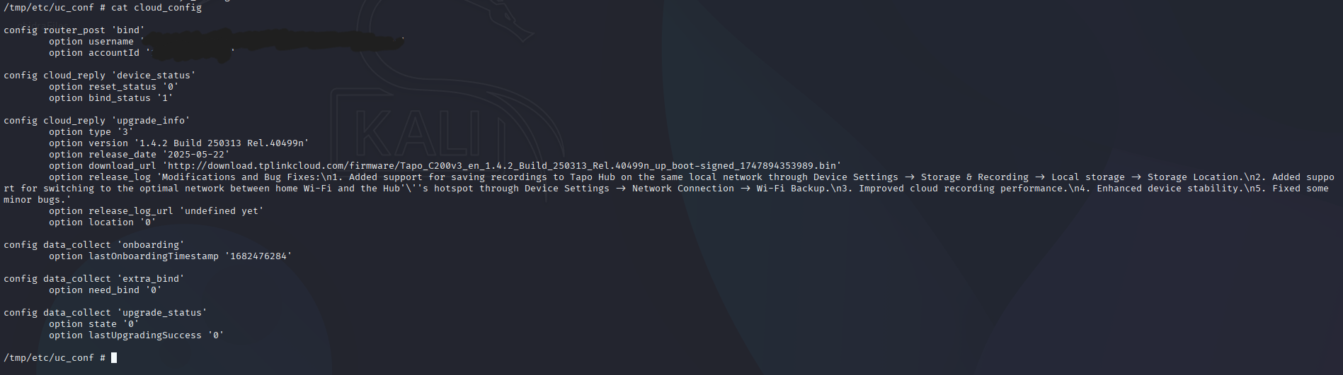
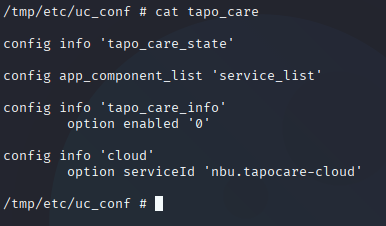
Among the most noteworthy configuration files generated are:
- cloud: Handles the device’s connection and communication with TP-Link’s cloud services.
- tapo_care: Manages settings maybe related to Tapo Care, TP-Link’s subscription-based security and storage service.
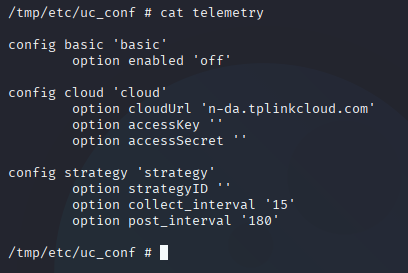
- telemetry: Contains data and parameters for device telemetry, likely used for diagnostics and remote monitoring.
- user_management: Stores user account information and access control settings.
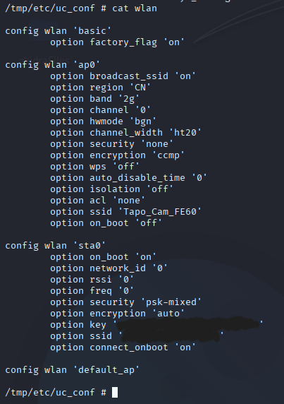
- wlan: Holds wireless network configuration, including SSID and security parameters.
These files provide valuable insight into the device’s operation, connectivity, and user management mechanisms.
####Configs

There are still several exciting areas left to explore, such as accessing the live video feed, intercepting communications with the cloud, and uncovering additional device internals. I’ll be diving into these advanced topics in the next installment of this blog series—stay tuned!